


Abstract
Additive manufacturing (AM), widely known as 3D printing, is a method of manufacturing that forms parts from powder, wire or sheets in a process that proceeds layer by layer. Many techniques (using many different names) have been developed to accomplish this via melting or solid-state joining. In this review, these techniques for producing metal parts are explored, with a focus on the science of metal AM: processing defects, heat transfer, solidification, solid-state precipitation, mechanical properties and post-processing metallurgy. The various metal AM techniques are compared, with analysis of the strengths and limitations of each. Only a few alloys have been developed for commercial production, but recent efforts are presented as a path for the ongoing development of new materials for AM processes.
Introduction and history
Additive manufacturing (AM), also known as three-dimensional (3D) printing, has grown and changed tremendously in the past 30 years since researchers in Austin, TX, started development of what is arguably the first machine in the lineage of metal AM: a laser used to selectively melt layers of polymer and, later, metal.1 The development of metal AM techniques has made great progress since then, but faces unique processing and materials development issues. Understanding the various processes used to make metal AM parts, and the issues associated with them, is critical to improving the capabilities of the hardware and the materials that are produced.
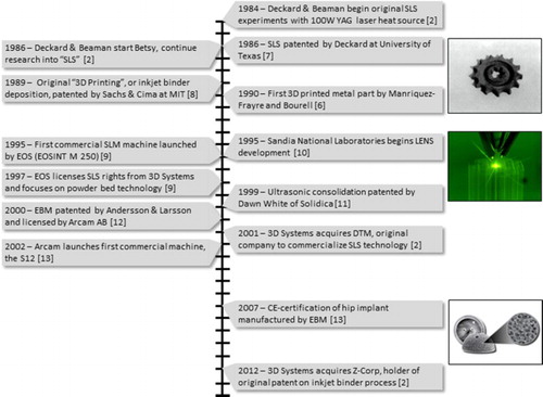
The first experiments directly relevant to metal AM started by forming polymer powder into 3D parts.2–5 This research focused on powder-bed laser sintering, which was patented and copyrighted as selective laser sintering (SLS). One of the earliest prototypes of SLS, ‘Betsy’, integrated the first automated powder distribution system. Arguably, the first reported metal ‘3D printed’ part was made from metal alloy powders (copper, tin, Pb–Sn solder) in an SLS process in 1990 by Manriquez-Frayre and Bourell.6 Today, systems used to make metal parts are typically referred to by selective laser melting (SLM) because full melting of the metal powder is achieved, whereas the term SLS is typically used to refer to polymer powder-bed processes only. Metal powder-bed processes have been called SLM, direct metal laser sintering, etc. depending on vendor. The term SLM is used throughout this work to refer to all metal powder-bed processes that use a laser as a heat source. This process is under licence by EOS GmbH, though other companies have entered the market with laser powder-bed hardware for metal production (SLM Solutions, Concept Laser, Renishaw, 3D Systems). Shortly after SLS was patented, a group of researchers at MIT patented a process called ‘three-dimensional printing’, which used inkjet printing to deposit binder. The use of ‘3D printing’ has evolved in popular media to describe all forms of AM, while the MIT method has become known as Binder Jetting. Binder Jetting can be used to create metal parts, in addition to other materials. Another class of printers relies on depositing feedstock directly into a molten pool, as opposed to selective melting of a powder bed. Known as direct energy deposition (DED), some of these machines are fed by wire and trace their history to welding technologies. In 1995, Sandia National Laboratories developed a different approach to feed powder feedstock into DED with a laser heat source. This technology was first commercialised and trademarked as laser engineered net shaping (LENS), a sub-set of DED. The last major category of metal AM, Sheet Lamination, welds together sheets of feedstock to form 3D parts. A process that uses ultrasonic welding and computer numerical control (CNC) milling to accomplish this was originally developed and patented by Dawn White of Solidica in 1999. In 2000, research in Sweden led to the patent of another powder-bed technique: electron beam melting (EBM). This process was later licenced and developed by Arcam AB. This metal AM history is more concisely presented as a timeline (Fig. 1),2,6–13 with significant patents highlighted in Table 1.
The metallurgy and processing science of metal additive manufacturing
Published online:
07 March 20161 Timeline of significant events in metal AM development
1 Timeline of significant events in metal AM development
The metallurgy and processing science of metal additive manufacturing
Published online:
07 March 2016Table 1 Original patents for the various classifications of metal AM
Since the invention of the various metal AM processes, rigorous R&D and industry efforts have found some niche applications. Part repairs, biomedical implants, aerospace structures and high-temperature components highlight some of the current production use of the technologies. Despite rapid advances in hardware and software for AM, some big questions remain: What are the current limitations of the technology? Can those limits be overcome through comprehensive research and development? Are the governing physics different of the same as that of traditional manufacturing?
Classification of technologies
A diverse set of processes has been used to form feedstock (powder, sheets or wire) into 3D objects. All metal AM processes must consolidate the feedstock into a dense part. The consolidation may be achieved by melting or solid-state joining during the AM processes to achieve this. In order to discuss distinct classes of machines, the ASTM F42 Committee on Additive Manufacturing has issued a standard on process terminology.14 Of the seven F42 standard categories, the following four pertain to metal AM:
Powder bed fusion (PBF)
○ Selective laser melting (SLM)
○ Electron beam melting (EBM)
Direct energy deposition (DED)
○ Laser vs. e-beam
○ Wire fed vs. powder fed
Binder jetting
○ Infiltration
○ Consolidation
Sheet lamination
○ Ultrasonic additive manufacturing (UAM)
The other three categories specified in the standard do not currently apply to metal technologies: material extrusion, material jetting and vat photo-polymerisation. There are unique uses, strengths and challenges for each process. In this review, each category for metal AM is briefly explored; however, more focus is given to DED and PBF due to the large volume of publications about these processes. Additionally, it should be noted that the term ‘SLM’ is used to refer to all laser PBF processes throughout this paper. This is the most widely used term for the process, so was adopted herein as convention.
Powder-bed fusion
PBF includes all processes where focused energy (electron beam or laser beam) is used to selectively melt or sinter a layer of a powder bed. For metals, melting is typically used instead of sintering. The use of laser sintering has been previously reviewed,15 but much progress has been made since this work to include the use of full melting. Re-melting of previous layers during the melting of the current layer allows for adherence of the current layer to the rest of the part. Schematics of PBF laser melting (SLM) and EBM machines are shown in Figs. 2 and 3, respectively. Although both systems use the same powder-bed principle for layer-wise selective melting, there are significant differences in the hardware set-up. The EBM system is essentially a high-powered scanning electron microscope (SEM), which requires a filament, magnetic coils to collimate and deflect the beam spatially, and an electron beam column. SLM typically has a system of lenses and a scanning mirror or galvanometer to manoeuver the position of the beam. Powder distribution is handled differently as well; SLM systems typically use a powder hopper or feeding system and soft distribution ‘recoater’ blades that drag powder across the build surface (other systems may use a dispersing piston and roller), while EBM systems use powder hoppers and a metal rake. Both EBM and SLM processes require certain steps: machine set-up, operation, powder recovery and substrate removal.
The metallurgy and processing science of metal additive manufacturing
Published online:
07 March 20162 SLM system schematic.252 Image courtesy of CustomPartNet Inc.
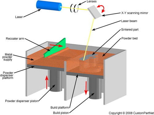
2 SLM system schematic.252 Image courtesy of CustomPartNet Inc.
The metallurgy and processing science of metal additive manufacturing
Published online:
07 March 20163 EBM system schematic.253 Courtesy of Arcam AB
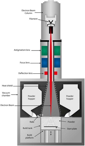
3 EBM system schematic.253 Courtesy of Arcam AB
A PBF machine requires a build substrate, or ‘start plate’, to give mechanical and thermal support to the build material. SLM processes bolt or clamp down the substrate, whereas the EBM process typically sinters powder surrounding the plate to provide stability (prevents the plate from becoming displaced by the rake blade). When successive layers of powder are distributed (rolled or raked out), existing layers of the build must not move; the substrate helps provide mechanical support. The substrate also provides a thermal path to dissipate heat, which is especially important for building overhangs on top of loose powder (prone to swelling and other process defects cause by local temperature fluctuations).
The operation of a PBF machine is governed by the details of the scan strategy and processing parameters, which will be discussed later in more detail. After the build is complete, excess powder must be removed from the build chamber. For EBM parts, this powder is passed through a powder recovery system to remove and recover sintered powder from around the parts. For SLM processes, powder surrounding the parts does not sinter as much and can be sifted directly to remove sintered clusters. Depending on the PBF process material, the build substrate may adhere to the parts.16 The substrate must be cut off, with abrasive saws and wire EDM being common methods. For some material combinations like Ti–Al–4V deposit and stainless steel substrate in EBM, material properties promote poor adherence; the parts fall off the substrate after the build, or can be easily removed by applied force. Parts coming directly out of the machine are considered ‘as-fabricated’.
PBF processes almost exclusively process pre-alloyed (PA) materials, directly achieving high densities. Prior work has been done to examine infiltration of more porous PBF materials.17 For example, bronze infiltration of laser sintered PBF parts has been demonstrated, with significant focus on porosity and the amount of infiltration.18 This is not typically desired, as infiltration alters the chemistry of a material and limits the range of available alloys and properties.
Direct energy deposition
DEDencompasses all processes where focused energy generates a melt pool into which feedstock is deposited. This process can use a laser, arc or e-beam heat source. The feedstock used can be either powder (Fig. 4) or wire (Fig. 5). The origins of this category can be traced to welding technology, where material can be deposited outside a build environment by flowing a shield gas over the melt pool.
The metallurgy and processing science of metal additive manufacturing
Published online:
07 March 20164 Laser, powder-fed DED system (LENS).20 Courtesy of the Welding Journal
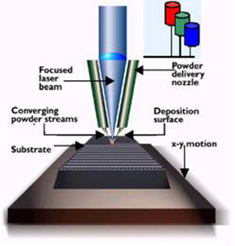
4 Laser, powder-fed DED system (LENS).20 Courtesy of the Welding Journal
The metallurgy and processing science of metal additive manufacturing
Published online:
07 March 20165 Electron beam, wire-fed DED system.214 Courtesy of Sciaky, Inc.
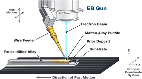
5 Electron beam, wire-fed DED system.214 Courtesy of Sciaky, Inc.
One of the most studied and commercialised forms of DED is accomplished using a laser heat source to melt a stream of powder feedstock (powder-fed). This DED sub-set was developed at Sandia National Laboratories and originally patented as the LENS process.19,20 Other DED processes feed wire into a molten pool (wire-fed), and are essentially extensions of welding technology.21,22 In fact, the use of modified welding machines to make DED parts via multi-pass welding is presently being explored.23 Applications of wire-fed, arc heat source DED have shown promise for successfully build some large geometries24 by utilising lower heat input values that can typically lead to porosity generation in this process.25
Machine set-up is relatively simple; machine software automatically checks most sensors. As in PBF, powder hoppers must be filled and a build substrate positioned. The substrate can be positioned in a stationary position (3−axis systems) or on a rotating stage (5+ axis systems) to increase the ability of the machine to process more complex geometries. In powder-fed systems, the feed rate of the powder must be verified regularly. If flow is impeded, nozzle cleaning or other maintenance may be performed. The build chamber is enclosed to provide laser safety, but the chamber is not necessarily filled with inert gas. For non-reactive metals, a shield gas directed at the melt pool may provide adequate safety and resistance to oxidation. For reactive metals, including titanium and niobium, the chamber is flooded with an inert gas (argon or nitrogen). A vacuum pump and purge cycles may be used to reduce oxygen partial pressure. Cyclic purging can consume a significant amount of inert gas, as the build chamber is much larger than those in PBF systems.
As in PBF, a finished DED part is typically attached to the build substrate. Parts are then post-processed both thermally (to reduce residual stress and improve properties) and mechanically to achieve the desired final geometry (parts produced using DED are typically near-net shapes with a rough finish). Parts may be removed from the substrate using the same processes for an adhered PBF part. Excess powder from machine operation is vacuumed during clean out of the machine. Depending on the operating procedure, this powder may be recovered or disposed. Disposal is usually a costly option, as powder costs are typically high. When paired with post-process machining, DED can be a powerful technique for repairing damaged parts (this is addressed further in the ‘Surface finishing’ section along with surface finishing and hybrid processing).
Binder Jetting
Binder Jetting works by depositing binder on metal powder, curing the binder to hold the powder together, sintering or consolidating the bound powder and (optionally) infiltrating with a second metal. A schematic of the binder deposition process is shown in Fig. 6. Infiltration achieves dense material by using a lower melting temperature alloy to infiltrate the printed structure. In contrast, the consolidation process can achieve uniform composition of a single alloy. Porosity is a major concern with these parts, as Binder Jetting is essentially a powder metallurgy (PM) process. Future development of Binder Jetting technology will benefit from extensive previous work in PM and ceramics. ExOne is currently the main manufacturer of Binder Jetting printers, so discussion of these devices is focused on this hardware.
The metallurgy and processing science of metal additive manufacturing
Published online:
07 March 20166 Binder Jetting process schematic.254 Image courtesy of CustomPartNet Inc.
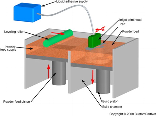
6 Binder Jetting process schematic.254 Image courtesy of CustomPartNet Inc.
The most common process used by these printers has focused on bronze infiltration of porous iron produced using a binder-sintering process. Binder Jetting printers selectively deposit liquid binder on top of metal powder using an inkjet print head. When the binder dries, a fragile binder–metal mix (also referred to as a ‘green body’) can be removed from the powder-bed system. The green body can then be cured to give mechanical strength, which can take 6–12 hours. After curing, the part is then heat treated at ∼1100°C for 24–36 hours to sinter the loose powder and to burn off binder, leaving a 60% dense sintered metal part. Infiltration occurs when the partially sintered material is placed in contact with a molten pool of a second material with a lower melting temperature than that of the sintered material. This allows infiltration of the liquid metal into the pre-sintered structure by capillary action to form a more dense part. Bronze infiltration of stainless steel can achieve a final density of 95%. A furnace cool is used to anneal the part and increase ductility.26 Infiltration is not unique to Binder Jetting, but is a common method for commercial production.
Consolidation is an alternate process to infiltration that can be used to produce solid alloys. The process works by designing in distortion of the part geometry to accommodate uniform shrinkage during sintering. This designed distortion is not well understood for the process, so unexpected ‘sagging’ or non-uniform consolidation may occur. The part is sintered until the metal consolidates into the desired final part geometry. Inconel 625 has been recently developed for Binder Jetting by ExOne, and is likely just the start of the development of additional consolidated metals for the platform. The material properties of the consolidated parts have not been published, so the quality cannot be currently compared to other AM methods. Surface finish is in line with many PBF processes. The surface finish of parts after annealing is quoted at 15 μm [Ra], and post-processing is quoted to reduce roughness to 1·25 μm [Ra].26
It is interesting to note that there are only limited published works with reference to Binder Jetting than for PBF and DED. Therefore, a detailed description of processing details is not addressed in this review. However, many research topics need to be addressed in the future, including binder burn off, geometrical accuracy during consolidation and unique infiltration materials.
Sheet Lamination
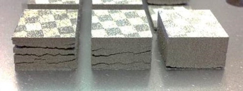
Sheet Lamination uses stacking of precision cut metal sheets into 2D part slices from a 3D object.27,28 After stacking, these sheets are either adhesively joined or metallurgically bonded using brazing, diffusion bonding,29 laser welding,30 resistance welding31 or ultrasonic consolidation. A key feature of Sheet Lamination hardware is the order in which sheets are applied and cut/machined. Sheets may be either cut to the specified geometry prior to adhesion or machined post-adhesion. Some of the advantages of the Sheet Lamination process include low geometric distortion (the original metal sheets retain their properties), ease of making large-scale (0·5 m × 0·8 m × 0·5 m) parts, relatively good surface finish and low costs. However, Sheet Lamination does have some limitations. Adhesively joined parts may not work well in shear and tensile loading conditions. Geometric accuracy in the Z-direction is difficult to obtain due to swelling effects.32 Finally, anisotropic properties are prevalent in Sheet Lamination builds due to the type of joining processes.
Steps involved in a brazing Sheet Lamination process are shown in Fig. 7.33 The sheets in this example are coated with flux (or low melting alloy), which acts as a brazing alloy for joining these sheets. In another process, special fixtures (Fig. 8) have to be developed for resistance welding Sheet Lamination to enable joining of layers. Due to the previously mentioned limitations with Sheet Lamination methodology, researchers have considered other solid-state joining techniques between sheets to improve the process. In 2003, White developed an innovative Sheet Lamination process in which the sheets were joined together by an ultrasonic seam welding technique known as UAM.34 The UAM process is one of the most used technologies for metal Sheet Lamination, so more technical details are included to illustrate the technology.
The metallurgy and processing science of metal additive manufacturing
Published online:
07 March 20167 Schematic illustration of sheet lamination process to make injection or metal forming moulds (we need permission to use this diagram)33
7 Schematic illustration of sheet lamination process to make injection or metal forming moulds (we need permission to use this diagram)33
The metallurgy and processing science of metal additive manufacturing
Published online:
07 March 20168 Sheet lamination methodology with slip resistance welding to join sheets31
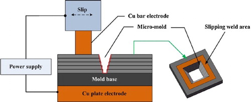
8 Sheet lamination methodology with slip resistance welding to join sheets31
Typical UAM process steps are listed below35:
Mill the substrate to achieve a flat surface
Blow off the substrate to remove tailings
Deposit material for a given layer in metal tapes through ultrasonic welding
Trim the edges of tape from the given layer to match the desired part geometry
Iterate layers until part is finished
Fine milling may be used, as required, to produce channels, holes or other features.
A schematic illustration of the process is shown in Fig. 9. Research36–38 has been performed in scaling this process to higher power for difficult to join metals including titanium, copper,39 stainless steel, metal-matrix composites, shape memory alloys40 and the dissimilar combinations thereof. Schick et al.,41 Dehoff and Babu42 and Fujii et al.43 demonstrated that the interfaces that had good metallurgical bonding always had a recrystallisation grain texture.
The metallurgy and processing science of metal additive manufacturing
Published online:
07 March 20169 The UAM process forms solid metal by a ultrasonic welding of metal tape onto a substrate or other tape layers and b machining or parts edges, channels, or features as needed through the process.255 © [EWI, 2010]
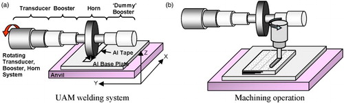
9 The UAM process forms solid metal by a ultrasonic welding of metal tape onto a substrate or other tape layers and b machining or parts edges, channels, or features as needed through the process.255 © [EWI, 2010]
The evolution of grain texture in UAM was postulated (Fig. 10) as a function of steps.43 Steps 1–3 show that the interaction of the sonotrode leads to the formation of asperities on the surface of the first tape, as well as associated recrystallisation texture due to adiabatic heating. Steps 4–8 postulate different steps that lead to bonding of the second tape to the first tape which involves plastic flow of the bottom region of the second tape into the asperities on the top of the first tape created in Steps 1–3. This process is repeated to build a 3D component. In Step 1, the sonotrode with rough surfaces makes contact with smooth Al-tape. On vibration at 20 kHz with normal loading, the surfaces of the Al-tapes deform adiabatically (Step 2). The deformation-induced local (region of depth ∼20 µm) heating promotes rapid recrystallisation of the deformed grains. In Step 4, a second Al-tape is abutted against this first tape and the process is repeated. This high-strain rate adiabatic heating and on-set of grain boundary motion across the original interface during recrystallisation leads to metallurgical bonding. Interestingly, this sequence of events is supported by the presence of shear texture at the interfaces. Persistence of shear texture and its effect on grain growth at high temperatures were analysed by Sojiphan et al.44 Interestingly, the grains with shear texture at the interface were found to be extremely stable.
The metallurgy and processing science of metal additive manufacturing
Published online:
07 March 201610 Schematic illustration of microstructural evolution during UAM43
10 Schematic illustration of microstructural evolution during UAM43
Although the process introduces high temperature (interface temperature may increase as much as 380°C during consolidation) within the localised region of the interface (∼20 µm),45 the overall temperature increase within the whole build is very low and the process temperature typically remains around room temperature. As a result, this process has been used for AM of dissimilar metals as well as embedding of actuators and sensors into parts.46
From this brief summary of Sheet Lamination, it can be seen that there are various techniques to accomplish bonding of metal sheets (brazing, resistance welding, etc.). Consolidation using ultrasonic welding through UAM surfaced as one of the most promising techniques for accomplishing Sheet Lamination, and a significant body of work exists on the subject. Interface metallurgy is particularly important for understanding the properties of the resulting material. Sheet Lamination is particularly useful for making metal composites by alternating sheets of dissimilar metal during consolidation. Pairing of machining with the consolidation process is common (de facto in UAM) and produces parts with machined surface finish directly from the hybrid process. However, the process cannot manufacture complex overhangs, as no support material is deposited to provide mechanical support.47 Features may be additionally limited by the tool paths available for machining operations.
Material processing issues
Although PBF and DED processes have significant differences, there are some common materials processing issues that occur in both platforms. These issues are explored, noting differences between categories of equipment where appropriate. As with traditional processing methods (casting, welding, etc.), porosity is a common concern in metal AM. Other defects (residual stress, delamination, cracking, swelling, etc.) are unique to welding or metal AM. The scan strategy, process temperature, feedstock, build chamber atmosphere and many other inputs determine the occurrence and quantity of defects. Understanding defects, and how they arise, can help operators improve process reliability and the quality of parts produced.
In order to understand the complex relationship between basic processing science, defects, and the product of an AM process, it is useful to consider a general process flow chart (Fig. 11). The process inputs are AM hardware and software, part geometry, scan strategy, build chamber atmosphere and feedstock quality. The process outputs are mechanical properties (static and dynamic), minimisation of failed builds and geometric conformity (feature size, geometry scaling). In the flow chart, a box encloses thermal interactions due to applied energy, beam interactions, heat transfer and process temperature. These interactions, if properly modelled, should be able to describe dynamic process temperature, which is one of the most (if not the most) defining quantity of metal AM processing. In the following sections, the above issues are all discussed.
The metallurgy and processing science of metal additive manufacturing
Published online:
07 March 201611 Focus of current review: overview of relationship between input parameters and underlying physics to meet the expected outcome of metal AM
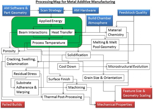
11 Focus of current review: overview of relationship between input parameters and underlying physics to meet the expected outcome of metal AM
Feature size, surface finish and geometry scaling
When printing metal parts, the minimum feature size, surface roughness and geometrical accuracy of the part are typical concerns for equipment operators, but overemphasis of these properties is not useful for most applications because the part surface will ultimately be machined (final finish) after thermal post-processing. The minimum feature size is determined by the minimum diameter of the heat source and the size of the feedstock. These data are summarised in Table 2. It can be seen that PBF typically has the best resolution, with the resolution of SLM slightly better than EBM depending on parameters used. Powder-fed DED has better resolution than wire-fed DED, which can be attributed to the use of finer feedstock (powder vs. wire). The feature size of DED systems is so large that parts made with these techniques are limited to more simple geometries than PBF techniques. Smaller feature sizes and smaller layer thickness currently come at the expense of deposition rate. The deposition rates of various technologies are explored in more detail later in this paper. Due to small feature size and the low inertia to changing the position of the beam, PBF techniques can utilise the minimum feature size to print metal mesh or foam structures. These structures melt metal ‘struts’, typically the size of an individual pulse of the heat source. Mesh parts have been well studied and reviewed elsewhere.48,49
The metallurgy and processing science of metal additive manufacturing
Published online:
07 March 2016Table 2 Typcial layer thicknesses and minimum feature sizes of PBF and DED processes
There are two separate contributors to surface roughness as shown in Fig. 12: (1) non-flat layer edges or layer roughness and (2) the actual roughness of the metal surface. The layering effect can be reduced by using smaller layer thickness values. This usually means longer build times because the layer thickness dictates the division of a part into a number of layers. The actual roughness of a material depends upon the details of the machine producing the part. DED typically has larger layer thickness, which mostly limits this technology to near-net shapes (shapes produced close to the desired part geometry, but intended to be machined to deliver the final geometry and details). Near-net shape processing is different from traditional subtractive methods where a full block of material is machined down to a final part. PBF systems typically have finer resolution and layer thickness, but are prone to satellite formation50 due to the sintering of powder at the part edges. Finer powder means smaller satellites and less surface roughness. SLM machines use finer powder and smaller layer thickness than EBM, which results in less surface roughness.
The metallurgy and processing science of metal additive manufacturing
Published online:
07 March 201612 Sketch of the contributions to surface finish by a layer roughness and b actual surface roughness
12 Sketch of the contributions to surface finish by a layer roughness and b actual surface roughness
Geometrical accuracy can be measured by taking 3D laser scans (or similar technique) and calculating the deviation relative to the original part file. Typical corrections are empirical modifications to scale part files in a Cartesian system. For example, an x-dimension of a part might be smaller than intended by some scaling factor. The scaling factor is then used to increase the x-axis length in the part file, before printing. This is typically accounted for during machine calibration. Post-fabrication machining is typically used for SLM, EBM and DED parts, as even the best achievable surface finish is still not as good as a machined finish. If machining is used, the actual part tolerance, surface finish and minimum feature size of AM parts are dictated by the machining step. For this reason, work to refine surface finish using smaller powder particles and smaller layer thicknesses may just add process time and cost (the smaller the layer, the more layers must be processed) without improving the quality of the final part.
Build chamber atmosphere
The atmosphere under which metal is processed strongly affects chemistry, processability and heat transfer. Inert gas and/or vacuum systems are typically used, and each requirement leads to unique processing concerns. Most metal powders have a tendency to oxidise and collect moisture when exposed to air. At higher temperatures, this oxidation can be accelerated. For this reason, welding machines use inert shield gases. AM processes have the same need. As discussed previously, DED typically operates with a shield gas flowing over the melt surface and may operate under an inert atmosphere. SLM processes are typically run in an inert environment, with an atmosphere of argon or nitrogen filling or flowing over the build surface. The flow rate of the fill gas and the pathway of the flow have been shown to be important in porosity reduction in SLM Ti–6Al–4V.51 Small features may lead to heat concentration in SLM, which can cause localised oxidation.
The EBM process uses a heated filament (usually made of tungsten) to generate electrons, which requires a vacuum-capable build chamber to operate the machine (<5 × 10⁻² Pa chamber pressure, <5 × 10⁻⁴ Pa column pressure). During beam operation, a small quantity of helium is injected to reduce electrical charging of the build volume. This raises the pressure of the build chamber to ∼0·3 Pa during beam operation. Operating in a near-vacuum environment leads to increased melt vapourisation and unique heat transfer consequences.
Feedstock quality
The quality of the feedstock that is used in the AM process is important to the quality of the final part. The quality of the powder is determined by size, shape, surface morphology, composition and amount of internal porosity. The quality of powder determines physical variables, such as flowability and apparent density. There are a variety of atomisation techniques for producing metal powder, each producing distinct variations in powder quality. There are several unique quality issues related to wire feedstock for DED as well. By understanding feedstock quality, an operator can select the optimal material for processing in a given system. Further information on the standards associated with quantifying powder characteristics and the details of powder science are well described elsewhere.52
The quality of powder is directly related to the production technique. A variety of techniques are used: gas atomisation (GA), rotary atomisation (RA), plasma rotating electrode process (PREP), plasma atomisation (PA) and others. Some atomisation techniques yield irregular shapes (like RA), others have a large amount of satellites (like GA) and some are highly spherical and smooth (like PREP and PA). Fig. 13 shows powder surface morphology and shape, as well as cross-sections to analyse internal porosity. Porosity in the powder feedstock is common for certain production techniques, like gas-atomisation (GA), that entrap inert gas during production. This entrapped gas is transferred to the part, due to rapid solidification, and results in powder-induced porosity in the fabricated material. These pores are spherical, resulting from the vapour pressure of the entrapped gas. Higher quality powders produced via the PREP do not contain such pores and have been used to eliminate powder-induced porosity in DED and PBF systems.16,53,54
The metallurgy and processing science of metal additive manufacturing
Published online:
07 March 201613 Comparison of powder quality before use: a SEM 250× of GA, b SEM 500× of GA, c LOM of GA, d SEM 200× of RA, e SEM 500× of RA, f LOM of RA, g SEM 200× of PREP, h SEM 500× of PREP, i LOM of PREP (used with permission)16
13 Comparison of powder quality before use: a SEM 250× of GA, b SEM 500× of GA, c LOM of GA, d SEM 200× of RA, e SEM 500× of RA, f LOM of RA, g SEM 200× of PREP, h SEM 500× of PREP, i LOM of PREP (used with permission)16
Work to use lower cost (and lower quality) powder produced using a hydride–dehydride (HdH) process in the EBM process has demonstrated that this powder type can lead to issues with porosity.55 Hot isostatic pressing (HIP) and a special ‘double melt’ technique were used to reduce porosity in both HdH- and HdH-blended powders. This work demonstrates both the importance of powder quality to microstructure and the ability to use both processing and post-processing to overcome feedstock issues. A thorough survey of the many powder types used for laser processes exists,56 regarding the research available on specific powder alloys.
Flowability (how well a powder flows) and apparent density (how well a powder packs) are important quantitative powder characteristics that are directly related to qualitative characteristics. A Hall Flow meter can be used to measure flow rate (flowability)57 and apparent density58 according to ASTM standards B213-13 and B212-13, respectively. Spherical particles improve flowability and apparent density. Smooth particle surfaces are better than surfaces with satellites or other defects. Fine particles, or ‘fines’, typically improve apparent density by filling interstitial space between larger particles, but flowability may be reduced. A wider particle size distribution (more fines) in SLM of stainless steel 316L was observed to result in high density (>99%) across a wider range of process parameters (beam diameter, beam speed) than powder with a smaller particle size distribution.59 Segregation of fines was observed in an SLM powder recycling study by researchers at NIST.60 It was found that large particles (>60 um) were preferentially raked out of the build area and not incorporated into the build; the particle size distribution after sieving shifted correspondingly towards larger particles.
The nominal particle size distribution of powder used in SLM is 10–45 μm, in EBM is 45–106 μm61 and in DED is 20–200 μm.62 The main trade-off in the selection of powder size is cost vs. surface finish. Smaller particles tend to improve surface finish due to reduction of the size of satellites. However, smaller powder particles may cost more as a feedstock (than a larger size range) due to lower yields for smaller particles in powder production (depends on production technique). SLM uses a fine distribution of powder to improve surface finish by enabling shorter layer thicknesses (and reducing satellite formation). Based on the previously discussed Slotwinski et al.’s powder study,60 the finer powder distribution is mostly a utilisation issue; larger particles would not be well utilised in a fine layer SLM process. EBM uses slightly thicker layers and a correspondingly large size distribution. EBM can use smaller size distributions, with no noticeable effect on chemistry, material properties or microstructure.63 The effect of powder flowability on processability using various hardware is not well published; though it is understood as an important parameter by industrial producers of AM parts. PBF systems typically have a hardware-specific flowability that depends on the powder distribution method used. Very fine particles size distributions that do not have a measurable flowability may still be processable in some systems. Powder-fed DED systems must consider the effect of flowability on the ability of powder to feed into the carrier gas stream. Once in the stream, the powder flow rate has been observed to have little effect on particle speed during DED processing.64
Additionally, the chemical composition of the powder must remain within alloy-specific specifications. It is important to measure the elemental composition of recycled powder, to address evaporative losses, contamination from powder recovery (vacuums or grit blaster used in EBM) and reaction with oxygen, nitrogen or other gases. A recent study65 on powder recycling in EBM of Ti–6Al–4V showed that oxygen content increased from 0·08 to 0·19% by weight, aluminium content decreased from 6·47 to 6·37% and vanadium content decreased from 4·08 to 4·03% over 0 to 21 reuse cycles.65 Powder particles became less spherical with use, flowability improved with more reuse cycles (attributed to reduction of satellites and reduction in humidity), yield strength (YS) and ultimate tensile strength (UTS) increased with oxygen content, and elongation was unaffected by oxygen content. These results suggest that, for moderate powder recycling conditions, powder composition can remain within specification and mechanical properties will not be adversely affected. These results should not be misinterpreted; however, titanium and its alloys are well known66 to suffer embrittlement with increases in oxygen and nitrogen concentration. Depending on the feedstock material, oxidation and humidity control may be important for both wire and powder storage.
Wire feedstock for wire-fed DED processes has minimal defects compared to powder because the technology for wire making is transferrable from mature welding consumable supply chains. The diameter of wire used for wire-fed DED is typically on the order of 2·4 mm.67 Better quality wire will have less variation in wire diameter, which is similar to requirements for plastic extrusion printers that use plastic wire as a feedstock. Porosity is a common welding defect, and the quality of wire (e.g. adsorbed moisture and diameter variance) is known to affect the amount of porosity in the weld deposit.68 For reactive metal like titanium, surface adsorption and reactions with atmosphere may also cause defects. More notably, the presence of cracks or scratches on the wire surface may translate directly to porosity formation. Unlike powder production, gas porosity is not an issue in wire production. In a study of both powder and wire feedstock, it was noted that powder had porosity, whereas the wire did not.69
Beam–powder interactions
The interactions of the heat source with the feedstock or melt pool impacts the utilisation of energy and can lead to liquid metal ejection and porosity. There are four basic modes of particle ejection during beam melting processes: (1) convective transport of liquid or vapourised metal out of the melt pool (or spatter ejection), (2) electrostatic repulsion of powder particles in EBM, (3) kinetic recoil of powder in DED and (4) enhanced convection of powder in gas streams. Lasers incur intensity losses due to reflection, whereas e-beams incur backscatter losses of electrons. E-beams systems must be designed to reduce electrical charge build-up. DED systems must also be designed to consider the effective feed rate of the feedstock, as appropriate amounts of deposit material must be delivered.
The convective transport of liquid or vapour out of the melt pool is commonly called ‘spatter’ or ‘spatter ejection’ and is seen in PBF, DED and welding. This is caused by the application of a high-energy beam creating localised boiling, where the energy of the ejected droplet must overcome surface tension forces.70 These particles can be identified in PBF and DED by the high-temperature emission of white or other light, which is the reason that these ejected droplets are sometimes referred to as ‘fireworks’.
A laser imparts energy to the powder bed via photons. Laser techniques must therefore compensate for the reflectivity/absorptivity71 of the metal powder, as some of the applied energy will not be absorbed. Depending on the metal, this may be a significant limitation. Higher power lasers are typically used to overcome this barrier to melting, but the higher laser power can lead to increased spatter ejection.72 Pulse shaping, or the control of the shape of the laser power profile, has shown promise for increasing energy absorption and decreasing spatter ejection in SLM.50 Pulse shaping can be used to more slowly heat a melt area (effectively a preheat), which can cause a decrease in reflectivity associated with higher temperatures. As laser control software and hardware improves, this technique may prove useful.
In the EBM process, electrons interact with the material to transfer not just energy, but also electrical charge. If repulsive electrostatic forces are greater than the forces holding particles to the powder bed, powder particles may be ejected from the powder bed.73 This effect can cause the bulk displacement of powder (Fig. 14) within the powder bed, known as ‘smoking’, if sintering is not properly achieved.74,75 The electrostatic ejection of powder particles can be reduced in EBM by using a rapidly scanned, diffuse beam to slightly sinter the melt surface prior to melting. Small quantities of helium gas are also injected during melting to dissipate charge from the melt surface. The ratio of the bulk density to the electrical resistivity of the powder has been identified as important for the reduction of powder ejection in EBM.73 Pre-sintering in SLM systems is not necessary, as photons do not cause charge build-up.
The metallurgy and processing science of metal additive manufacturing
Published online:
07 March 201614 An event of ‘smoking’ caused by electrostatic repulsion: a distributed powder bed, b applied beam and c ‘smoking’ or a cloud of charged powder particles75
14 An event of ‘smoking’ caused by electrostatic repulsion: a distributed powder bed, b applied beam and c ‘smoking’ or a cloud of charged powder particles75
Powder may also be removed by kinetic recoil (powder-fed DED) and convection of powder in the fill or shield gas steam (LM or powder-fed DED). As the stream of powder particles is sprayed into the melt pool during DED, some particles will recoil and avoid deposition. This loss is typically adjusted for experimentally, but can be a significant loss of powder (if not recovered). Small traces of powder may appear as ‘dust’ present in the fill gas of inert atmosphere processes. Particles lost in this way have not been quantified, though are probably not significant compared to other loss mechanisms. Both kinetic recoil and convection of powder do not directly remove particles from the melt pool, which means that these mechanisms are not of likely importance for control of porosity. Electrostatic repulsion is mostly an operational concern, but may lead to some porosity. Spatter ejection is known to result in weld defects and is an underlying mechanism for the formation of some forms of process-induced porosity.
Porosity
Porosity is a common defect in metal AM parts and can negatively affect mechanical properties. Porosity can be powder induced, process-induced or an artefact of solidification (compared in Fig. 15).16 As previously discussed, gas pores may form inside the powder feedstock during powder atomisation. These spherical, gas pores can translate directly to the as-fabricated parts. For most studies, porosity formation is dominated by processing technique. Process parameters must be properly tuned to avoid a range of mechanisms that can create pores.
The metallurgy and processing science of metal additive manufacturing
Published online:
07 March 201615 Light optical microscopy showing comparison of process-induced, lack of fusion porosity to entrapped, gas porosity transferred from the powder feedstock16
15 Light optical microscopy showing comparison of process-induced, lack of fusion porosity to entrapped, gas porosity transferred from the powder feedstock16
Pores formed by processing technique, known as process-induced porosity, are formed when the applied energy is not sufficient for complete melting or spatter ejection occurs. These pores are typically non-spherical, and come in a variety of sizes (sub-micron to macroscopic). Different processing issues can create defects in the material, some of which contribute to porosity. When not enough power is supplied to a region of powder, lack of fusion can occur. Lack of fusion regions may be identifiable by un-melted powder particles visible in or near the pore. When the applied power is too high, spatter ejection may occur in a process known as keyhole formation. It has been observed for SLM that operating within the keyhole mode can produce a trail of voids over the operating region.76 To limit spatter ejection, an operator will typically watch the process and tune parameters, while developing a new material processing strategy. Process-induced porosity has other contributors, including the effect of powder consolidation from a loosely packed powder bed to a fully dense part.77 Powder is distributed onto the processing surface and includes particles larger in diameter than the layer thickness, which upon melting are intended to consolidate into a layer of the correct height. Shrinkage porosity (sometimes termed ‘hot tearing’) is the incomplete flow of metal into the desired melt region. Spatter ejection may also lead to regions of porosity. With optimised melting parameters, process-induced porosity can be reduced to very low levels in DED, SLM and EBM (less than 1% porous).78–80 The relationships among lack of fusion, shrinkage regions and cracks have not been fully studied in AM material. However, work has been done to explore the effect of process parameters (beam speed and beam power) on the formation of process-induced and powder-induced porosity.81
Scan strategy
The path that the heat source follows during selective melting or deposition for lasers or electron beams is classified as the scan strategy. Various scan strategies have been developed and are depicted in Fig. 16. Scan strategies for DED tend to be relatively simple, limited by the movement of the powder or wire feeding system. Unidirectional (Fig. 16a) and bi-directional (Fig. 16b) fills are both standard DED processing techniques. These strategies use rectilinear infill to melt a given part layer. Both unidirectional and bidirectional fills are used in SLM and EBM, though improvements have been made. In SLM, island scanning (Fig. 16c) has been used to reduce residual stress.82 Island scanning is a checkerboard pattern of alternating unidirectional fills and reduces temperature gradients in the scan plane (x–y plane) by distributing the process heat. PBF systems tend to have lower inertia to beam movement than DED (due to no feeding mechanism) and can also melt in a pulsed, spot mode (Fig. 16d). This spot mode is typically used in EBM to melt contours (Fig. 16e), which are boundaries between infill and the powder bed. Contours follow the edges of the part, melting along free surfaces of the part geometry. SLM systems also used contours, though the contour melting strategy is typically linear (Fig. 16f). Contour passes are done after melting in SLM to refine surface finish,82 whereas the passes are done before melting in EBM. In EBM, the melt process heats up the build material; contours that are run after melting tend to form more satellites due to higher temperature, yielding a rougher surface finish. Most machines offer operators the choice of contour order and it is one of many parameters optimised by the machine manufacturer before releasing parameters for a material. The scan strategy for a given build may be adjusted by layer or by part. Unidirectional, bi-directional and island scanning strategies are typically rotated by an angle between each layer.
The metallurgy and processing science of metal additive manufacturing
Published online:
07 March 201616 Scan strategies used to determine heat source path in metal AM as seen in the X-Y plane (perpendicular to the build direction): a unidirectional or concurrent fill, b bi-directional, snaking, or countercurrent fill, c island scanning, d spot melting, e spot melting contours with snaking fill and f line melting contours with snaking fill
16 Scan strategies used to determine heat source path in metal AM as seen in the X-Y plane (perpendicular to the build direction): a unidirectional or concurrent fill, b bi-directional, snaking, or countercurrent fill, c island scanning, d spot melting, e spot melting contours with snaking fill and f line melting contours with snaking fill
The scan strategy has a direct impact on process parameters; heat source power and velocity must be optimised for a given scan strategy. The relationship between applied heat source power and the heat source velocity is a key parameter of PBF and DED processes and will be addressed in more detail with heat transfer, solidification and thermal cycles. This relationship is important for eliminating process-induced porosity and determining grain morphology.
Deposition strategy
The way in which feedstock is delivered to the melt surface determines deposition rate and can have a strong impact on material defect and properties. In wire-fed DED, the vertical angle ( ) and the horizontal angle ( ) of the wire feed are related to deposition efficiency, surface roughness, incomplete melting, rippling and other processing defects.69 Similarly, the angle for powder spraying is important to powder-fed processes. In both powder-fed and wire-fed DED, the deposition rate is critically important. The deposition rate and the velocity of the heat source both determine how much material is deposited in a given pass. In DED, the build-up of material must be considered to appropriately choose the z-axis layer height or layer thickness. In PBF, layer thickness determines how much powder is ‘raked’ or distributed to the melt surface. A ‘rake’ is a metal, ceramic or polymer-coated bar that sweeps out powder onto the build surface. The number of passes of the rake, mechanical type of rake and the amount of powder being retrieved per pass determine the efficiency of the PBF powder delivery system.
Cracking, delamination, & swelling
The formation of defects is essentially dependent on process temperature. Cracking of the microstructure may occur during solidification or subsequent heating. Macroscopic cracks may relate to other defects, including porosity. Delamination leading to interlayer cracking is shown in Fig. 17. If the process temperature is too high, a combination of melt pool size and surface tension may lead to swelling or melt balling. If processing conditions are tightly controlled, most of these defects can be avoided. Cracking of the microstructure is material dependent as well, and there may be some processing cases where cracking is unavoidable.
The metallurgy and processing science of metal additive manufacturing
Published online:
07 March 201617 Layer delamination and cracking can be a problem in SLM (shown for M2 tool steel)84
17 Layer delamination and cracking can be a problem in SLM (shown for M2 tool steel)84
There are different material-dependent mechanisms for which cracks form in AM material.82 Solidification cracking can occur for some materials if too much energy is applied and arises from the stress induced between solidified areas of the melt pool and areas that have yet to solidify. This type of cracking is dependent upon the solidification nature of the material (dendritic, cellular, planar) and is typically caused by high strain on the melt pool or insufficient flow of liquid to inadequate supply or flow obstruction by solidified grains.83 Higher applied energy leads to higher thermal gradients, which can explain the larger thermal stress required for solidification cracking. Grain boundary cracking is cracking that nucleates or occurs along grain boundaries of the material. The origins of this type of cracking are material dependent and depend on the formation or dissolution of precipitate phases and the grain boundary morphology. The process parameters required to minimise process-induced porosity may differ from those required to minimise the formation of cracks.82 Solidification cracking and grain boundary cracking are both phenomena that occur within the microstructure. More generally, cracking is sometimes used to describe macroscopic cracks in the material. These cracks may nucleate due to other macroscopic defects such as delamination that are not related to excessive energy input.84
Delamination is the separation of adjacent layers within parts due to incomplete melting between layers. This may occur due to incomplete melting of powder or insufficient re-melting of the underlying solid. Whereas the effects of lack-of-fusion defects may be localised within the interior of the part and mitigated with post-processing, the effects of delamination are macroscopic and cannot be repaired by post-processing. Reduction in macroscopic cracking has been demonstrated in SLM by using substrate heating.84
Excess energy input can lead to overheating of the material. This may occur due to small features or overhangs in the part geometry, as shown in Fig. 18. Overhangs in PBF are typically made using support structures such as wafers. Lattice support structures have been recently explored.85 There are two kinds of supports: mechanical support and thermal support. Mechanical supports help prevent overhangs from deformation from gravity or growth stresses. Thermal supports allow applied energy a conductive path away from the melt surface in PBF. Swelling is the rise of solid material above the plane of powder distribution and melting. This is similar to the humping phenomenon in welding and occurs due to surface tension effects related to the melt pool geometry.16 Melt ball formation is the solidification of melted material into spheres instead of solid layers, wetted onto the underlying part. Surface tension is the physical phenomenon that drives melt balling, which is directly related to melt pool dimensions.86 When the length–to-diameter ratio is greater than 2·1 (

The metallurgy and processing science of metal additive manufacturing
Published online:
07 March 201618 For EBM-printed Ti–6Al–4V parts, it can be seen that (left) a NIST test artefact designed to test AM capabilities has overhangs printed in the side of the part. This artefact is intended to test the ability of various machines to print overhangs. Minor swelling can be seen both above the overhang and near a hole on the left side on the top surface. (Right) A complex robotic part shows a slightly deformed overhang, with sintered powder and support stubs left underneath
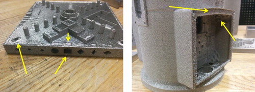
18 For EBM-printed Ti–6Al–4V parts, it can be seen that (left) a NIST test artefact designed to test AM capabilities has overhangs printed in the side of the part. This artefact is intended to test the ability of various machines to print overhangs. Minor swelling can be seen both above the overhang and near a hole on the left side on the top surface. (Right) A complex robotic part shows a slightly deformed overhang, with sintered powder and support stubs left underneath
The metallurgy and processing science of metal additive manufacturing
Published online:
07 March 201619 Melt ball formation and delamination in EBM stainless steel87
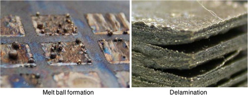
19 Melt ball formation and delamination in EBM stainless steel87
Substrate adherence and warping
The use of a substrate for the deposition of material is standard practice in DED and PBF but typically adds additional work during post-processing. Metal AM processes build on top of a metal substrate to achieve mechanical adherence of the first layers of the melted part.16 The substrate may be left at room temperature, heated by internal heaters, or heated by an electron beam. Most metal deposits form ductile interfaces and must be cut off the substrate during post-processing. Ti–6Al–4V deposited on Stainless Steel 304 substrate forms a more brittle interface that can be removed by application of force, without cutting. This kind of interface is desirable for decreasing the number of post-processing steps.
Substrates may warp during use as shown in Fig. 20.90 This can be due to the operating temperature of the AM process, the heat treatment of the substrate prior to use or due to differential coefficients of thermal expansion. Some processes use a substrate of the same material as the build, like stainless steel, to reduce this effect. The ultimate result of substrate warping is distortion of part geometry within the affected layers and possible lack-of-fusion or delamination at the transition region back to unaffected material. Substrate warping is a form of stress relief that results in permanent plastic deformation. Recent work to model substrate distortion has rationalised the progression of stresses with thermal history in EBM.91 The same mechanisms that cause substrate warping can also lead to major issues with residual stress.
The metallurgy and processing science of metal additive manufacturing
Published online:
07 March 201620 The effect of substrate warping can lead to lack-of-fusion or delamination90
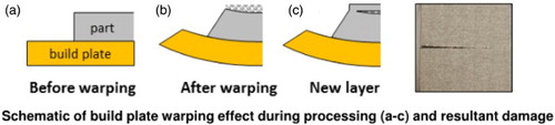
20 The effect of substrate warping can lead to lack-of-fusion or delamination90
Residual stress
Residual stress is common in metal AM materials due to large thermal gradients during processing, and it can negatively impact mechanical properties and act as a driving force for changes in grain structure. Residual stress is a stress within a material that persists after the removal of an applied stress. If this stress exceeds the local yield stress of material, warping or plastic deformation may occur. If this stress exceeds the local ultimate tensile strength of the material, cracking or other defects may occur. Macroscopic residual stresses can have a dramatic effect on the bulk behaviour of AM parts, whereas the effects of microscopic residual stresses from precipitates or atomic dislocations are more localised. Macroscopic residual stress can be thermally introduced in metal AM by (1) differential heating of the solid and (2) differential cooling during and after solidification.92 Residual stress is a concern because it can negatively affect the mechanical properties of as-fabricated parts or lead to geometrical distortions. A number of techniques have been applied to measure residual stress in AM parts and are discussed in this section. The magnitude of residual stress and the ways to reduce it are process dependent. Residual stress may influence recrystallisation, which is discussed in detail later with post-processing.
Residual stress tends to be compressive in the centre of DED and PBF parts, tensile at the edge, and more highly concentrated near the substrate interface.93–96 Axially, peak tensile residual stresses were measured near the top surface and were noted to be balanced by compressive stresses in the sample interior.93 Support structure, used to separate the build from the substrate, may slightly reduce residual stress due to having a higher initial temperature than the bare substrate.93 Upon removal from the substrate, residual stress is relieved but may result in deformation of the part.92 Modelling of thermal cycles for wire-fed DED using finite element methods has confirmed measurements of higher residual stress near the substrate interface.97
The effect of island scanning on residual stress has been studied.90,98 Island scanning in SLM was observed to reduce porosity in parts but lead to increased residual stress. Smaller islands resulted in lower tensile residual stress than larger islands, but continuous scanning resulted in the least amount of tensile residual stress. All scan strategies studied resulted in roughly equivalent compressive residual stress. This result is unexpected, as the purpose of an island scanning strategy is nominally to reduce residual stress. It was noted, however, that significant quantities of porosity in the continuous scanning samples existed and may act to self-relieve stress, complicating analysis; the lower amounts of residual stress observed in the continuous scanning samples may be due to the presence of other defects and the comparison to island scanning samples may not be direct.
Residual stress tends to be higher for substrates operated near room temperature (DED, SLM) than those operated at higher temperature (EBM). DED residual stress measurements using neutron diffraction have shown that residual stress in parts was 50–80% of the 0·2% yield stress.94 Heating of the substrate helps reduce residual stress, as does in situ heating of the material using the primary heat source.92 A defocused electron beam can operate with enough speed and power to accomplish this (and does via the preheat step) in EBM, but significant substrate heating using the heat source is not possible for most SLM and DED systems. As a result, SLM and DED parts generally have much more residual stress than EBM parts due to a lower operating temperature. The lower operating temperature means that thermal gradients between the peak melting temperature and the powder-bed temperature may be increased. Recent work has shown that residual stress in EBM parts is 5–10% of UTS (Fig. 21).95 The potential for multiple lasers to accomplish in situ process heating is addressed later, within the discussion of future AM systems. Understanding the origins of residual stress requires a more detailed knowledge of process thermal history, while understanding methods for eliminating or reducing residual stress will be discussed in more detail with post-processing.
The metallurgy and processing science of metal additive manufacturing
Published online:
07 March 201621 Work using neutron diffraction to measure residual stress in a–c) SLM and d–f EBM IN718 shows consistently lower residual stress in EBM samples than in SLM samples95
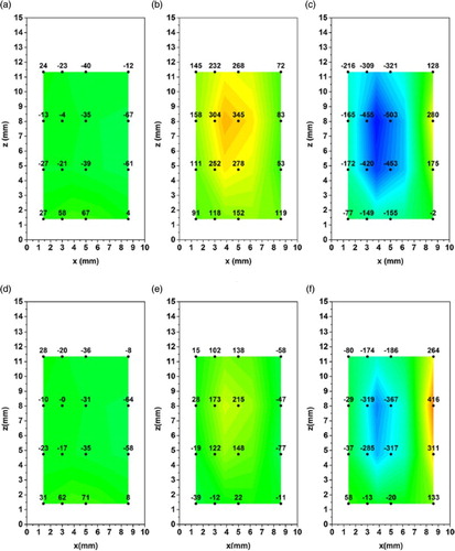
21 Work using neutron diffraction to measure residual stress in a–c) SLM and d–f EBM IN718 shows consistently lower residual stress in EBM samples than in SLM samples95
Residual stress can be measured using a variety of techniques: micro-hardness,99,100 the contour method,101 X-ray diffraction,92 neutron diffraction102 or other methods. For alloys that do not have significant precipitate hardening (single matrix phase), the shape of micro-hardness indents can be used to quantify the presence of residual stress. However, micro-hardness only reveals information about stress near the surface that is tested. The contour method is based on the deflection of surfaces after cutting (e.g. EDM), and this method provides comparable results to that of neutron diffraction.103 Additionally, the contour method is noted to be less chemistry dependent than neutron diffraction. X-ray diffraction and neutron diffraction can both be used to measure bulk stress variation, but are more expensive and require specialised equipment. Residual stress formation may also be modelled. Finite element analysis104 has demonstrated the ability to predict SLM residual stresses. Additionally, simplified thermal cycles have been shown to qualitatively match experimental results of substrate warping.105
Heat transfer, solidification and thermal cycles
The metallurgy of AM parts is determined by the feedstock chemistry and the temperatures that the material experiences, or the thermal history. There are different heat transfer mechanisms for different classifications of AM, but the use of full melting means that the metallurgical principles are the same for both DED and PBF. Solidification determines the initial phase distribution and grain morphology of the metal deposit. Heat source speed, power and size determine melt pool geometry, which in turn determines solidification kinetics. After solidification, thermal cycling and cool down path determine further precipitation kinetics, phase growth and grain growth.
Modes of heat transfer
It is important to understand how the modes of heat transfer differ between AM processes. DED processes transfer heat primarily through conduction to the substrate, conduction to the build material and convection to the shield gas. These modes of heat transfer are the same as those for welding. In SLM processes, conduction may be inhibited by powder acting as a thermal insulator surrounding the part. Additionally, the fill gas in SLM has a lower flow rate (argon gas consumption of 0·035–0·070 m3 h−1)106 than the shield gas in DED (0·354 m3 h−1).62 The actual flow rate of SLM cover gas may be higher than the gas consumption rate if recirculation is used (gas consumption only measures loss due to positive pressure or leakage), so it may be useful to consider local velocities across the surface (<2 m s−1) as calculated in recent modelling work.51 The higher flow rate in powder-fed DED systems is necessary, as the cover gas is also used for powder delivery (though this assumes primary gas flow for powder delivery and secondary gas flow for shielding are directly related or equal).62 This should result in reduced convective heat transfer in SLM when compared with DED.
EBM conduction mechanisms are similar to SLM, but the near-vacuum environment significantly reduces convective heat transfer during the melting process. This means that, for EBM processing, radiative loss from the build surface and conductive loss to the machine are the principle modes of heat transfer. Since EBM operates at elevated temperatures (400–1000°C), the thermal history of EBM material must be considered with respect to solidification and the hold temperature during the build. The fused metal solidifies from a molten pool and then is kept at elevated temperature until all layers have finished melting. DED and SLM processes may use heaters to increase the temperature of the build envelope to 100–200°C. This is intended to reduce residual stress and warping but is not high enough to significantly impact the phase and grain structure of typical AM alloys.
The mode of heat transfer can have important microscopic implications. For example, the depth of a melt pool is typically controlled by the conduction of heat from the melt pool to material underneath.76 However, keyhole mode formation of porosity can occur when the depth is controlled by metal evaporation. Being able to transition between calculations on this microscopic scale and calculations of bulk heat transfer is important and is discussed later along with computational modelling of metal AM processes.
Solidification
Solidification in DED and PBF is governed by the melt pool geometry, which is mostly determined by the relationship of the beam scan velocity to beam power. This relationship is extremely important and, using EBM as an example, may be defined by a function to select an appropriate scan speed based on beam power (or current). The relationship between beam speed and beam power must be defined in some way by the user, as only certain combinations of speed and power will result in dense material. The ‘speed function’ is such a relationship for EBM and is shown in Fig. 22.107 The slope and the translation of this relationship must position the selected speed and applied power within a certain processing window. Various combinations of speed and power allow for fully dense material (Fig. 23) that is free of defects. Similar process mapping of defects using heat source power and speed has been used in welding for years to map process windows as shown in Fig. 24. The relationship between speed and power is material-dependent and is important for process parameter mapping. SLM and DED define a simple, constant relationship between speed and power, whereas the EBM parameters account for differences in part geometry and other effects by dynamically changing the speed–power relationship.
The metallurgy and processing science of metal additive manufacturing
Published online:
07 March 201622 The relationship between speed and current for EBM is known as the ‘speed function’107
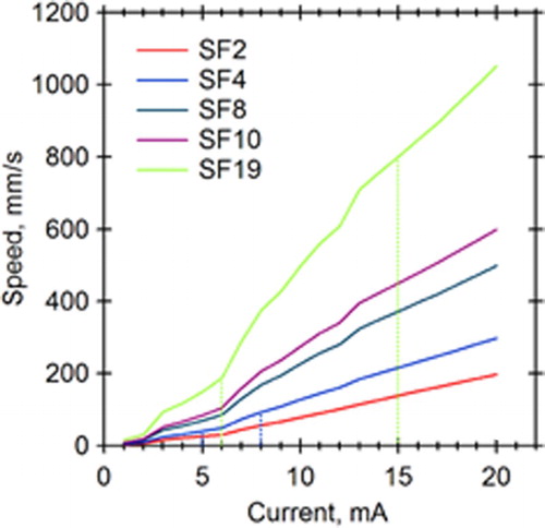
22 The relationship between speed and current for EBM is known as the ‘speed function’107
The metallurgy and processing science of metal additive manufacturing
Published online:
07 March 201623 Process map for stainless steel EBM demonstrates importance in the relationship between applied power and beam speed87
23 Process map for stainless steel EBM demonstrates importance in the relationship between applied power and beam speed87
The metallurgy and processing science of metal additive manufacturing
Published online:
07 March 201624 Relationship between effective power and speed in determining the weldability of Inconel 718256
24 Relationship between effective power and speed in determining the weldability of Inconel 718256
Speed–power relationship
The relationship between speed and power that is needed to avoid defects varies depending on several factors: edge effects, scan strategy, part geometry and thickness of powder beneath the scan area. All of these factors amount to changes in the initial conditions or boundary conditions for heat transfer. After a heat source passes near an edge, it may return to the edge before the heat from the previous pass has time to dissipate. The scan strategy can have a similar impact on heat flow, depending on how the strategy allows for cool down between each melting pass. Part geometry effects include those associated with a variation in the size of the part. A small part will reach a higher peak temperature during melting than a larger part, given constant power and speed. This can lead to more defects in smaller parts or features. For PBF, the state of the material underneath the melt area (powder vs. solid) can drastically affect heat transfer. A powder (non-sintered or sintered) has relatively poor thermal conductivity and can be considered thermally insulating compared to the solid part of the substrate. As heat is applied, it flows more slowly through the powder, which can lead to overheating of the melt surface located above the powder. The influence of all these phenomena means that applied power and speed alone may not be the best indicator of porosity due to local variations.108 In fact, the frequently utilised relationship of applied energy density has been noted to not be useful for certain cases of metal AM.47 In cases of high speed and high power, melt balling may occur. Process mapping was proposed and reference by authors Gibson et al. as a better way (than purely utilising applied energy density) to analyse metal AM processes.
Columnar-to-equiaxed transition
The power and speed of the heat source also affect the thermal gradient (G) and liquid–solid interface velocity (R) of the melt pool. The process window of solidification can be estimated for an AM process and used to predict the nature of the grain structure as shown in Fig. 25. The columnar-to-equiaxed transition (CET) can be calculated based on established methods109 and plotted for various materials.110 Recent work in PBF111 has been increasingly focused on controlling the CET and is addressed in a discussion of AM microstructures later in this paper. The CET can be transformed into a process map so that appropriate powers and velocities can be selected.112 Further work is needed to combine the maps for defects and the CET, so that the process space can be fully understood for each material.
The metallurgy and processing science of metal additive manufacturing
Published online:
07 March 201625 EBM processing window for Inconel 718 processing overlaid on G vs. R data117
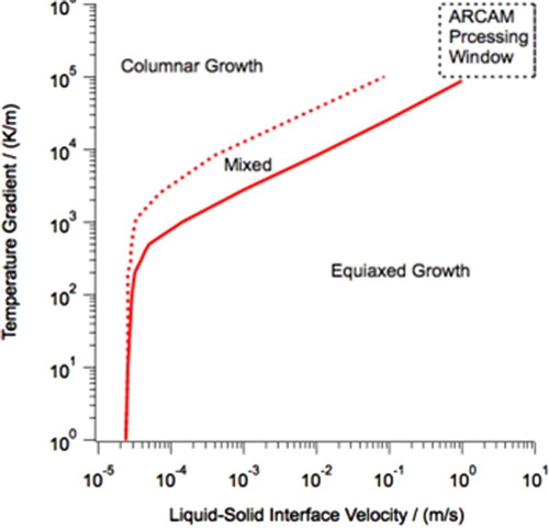
25 EBM processing window for Inconel 718 processing overlaid on G vs. R data117
Process thermal history
There are other consequences of melt pool geometry. Modelling has shown that poor powder thermal conductivity has a large impact on the size of the melt pool.113 The heat sources in PBF move so fast that recent work has suggested that though the heat source is a point, a linear heat source may be a reasonable approximation.114 Increasing beam diameter is a way to decrease thermal gradient of the melt pool and slow down solidification, but the effect of beam diameter on grain size has not yet been reported. The effect of beam diameter, measured as ‘focus offset’ in mA, has been related to melt pool width in EBM.107 Such work is beneficial to the development of accurate process modelling.
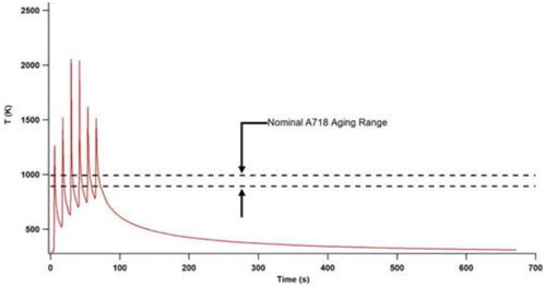
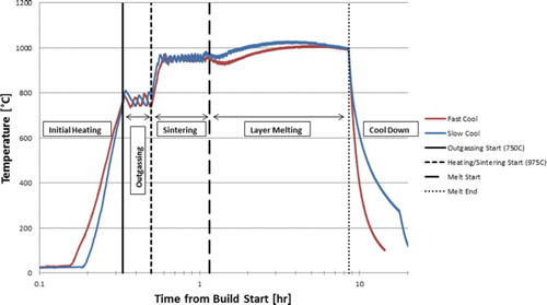
PBF and DED processes involve simultaneous melting of the top powder layer and re-melting of underlying layers. This creates thermal cycling, as the material reheats and cools. This cycling has been measured experimentally and modelled as shown in Fig. 26.115,116 DED and SLM are both typically performed at room temperature or close to it (heaters can get to 100–200°C); the material cools quickly, within seconds to minutes. In EBM, the process operates at an elevated temperature and experiences a distinct thermal history as measured by the substrate temperature in Fig. 27. The EBM process can take 5–80 hours to cool below 100°C after layer melting is completed, depending on part geometry.117 So, the effect of hold time and hold temperature on material properties must be considered for EBM. The impact on a precipitate hardened material like IN718 may be spending up to 100 hours (EBM) in the nominal aging range as opposed to ∼100 seconds (DED).
The metallurgy and processing science of metal additive manufacturing
Published online:
07 March 201626 Thermal simulation of a point during powder-fed DED showing cyclic heating cycles116
26 Thermal simulation of a point during powder-fed DED showing cyclic heating cycles116
The metallurgy and processing science of metal additive manufacturing
Published online:
07 March 201627 EBM process thermal history for Inconel 718, as measured by the machine-standard, substrate thermocouple117
27 EBM process thermal history for Inconel 718, as measured by the machine-standard, substrate thermocouple117
Modelling and Simulation
One of the primary goals of predictive modelling for AM is to reduce the need for experimental trial and error optimisation of processing recipes based on variable powder, design, energy input, path/layer sequencing and post-processing heat treatments. These experiments may span over several years and cost millions of dollars per each set of material powder/wire/tape combinations for a given process and might be part or geometry dependent to ensure certification. Given all these complex options for materials and processing, it is important to have a simulation capability and models that can predict part performance, support development of processing and materials strategies, and enable materials design in an integrated fashion. The prevailing hypothesis in academia, industry and national laboratories is to leverage existing integrated computational materials engineering (ICME) tools to address this challenge. However, there is limited maturity of ICME tools for AM that are capable of predicting thermo-mechanical cycles, solidification, solid-state transformation, residual stress, geometric distortion and mechanical properties as a function of existing and emerging AM processes. In this section, the current state of the art in modelling AM is reviewed and possible future directions are provided as to where this field might evolve.
There are various computational challenges that make modelling of AM processes difficult:
A large number of powder particles and melt passes comprise a typical machine processing volume; a 1-m3 processing volume includes ∼1012 particles and ∼109 m of weld line (assuming 50 μm particles)
In order to run typical welding simulations for a few minutes of beam duration on this volume, decades of computational time on a large cluster is needed as the time steps for stability are really small; exascale high-performance computing alone cannot address this issue (e.g. a sample simulation of one line of EBM with a scan speed of 4 m s−1 over a length of 1 mm for 0·2 ms translates to 200 steps with 10 µs time steps and takes 1272 seconds on a single processor)
Very large gradients in temperature as a function of space and time are a result of rapid heating and cooling; this means the region of interest must utilise a very fine mesh, but the majority of the processing volume is not in the region of interest
Highly heterogeneous and multi-scale as at any point in time, the region of interest is confined to a very small region
Hours of build with very small time steps is not tractable, as one cannot parallelise in time for these complex simulations
Accurate computational tools to predict the residual stress, geometry and quality of the build do not exist
Integrated and validated multi-physics capability that includes phase change dynamics including surface tension, residual stress, microstructure, etc. do not exist
Path optimisation in terms of beam path sequencing, beam speed, heat source focus and applied power as a function of space and time leads to an infinite dimensional parameter space that is difficult to manage computationally as well as experimentally
Large number of thermo-physical and other parameters along with missing understanding of beam interaction with the substrate, microstructural changes as a function of phase change dynamics, etc.
Validation is difficult as non-intrusive characterisation in current machine configurations is mostly limited to surface and boundary measurements through viewing windows118 or post-build characterisation of microstructures.
These challenges are in some ways analogous to computational weld mechanics but are also different as the problem is many orders of magnitude more complex than that of the welding and thus requires fresh approaches to tackle the problem. For reference, the state of the art in computational weld mechanics attempts to simulate at most meters of weld line and the thermal gradients are not that severe as the energy input paths are much wider. In this section, ongoing modelling efforts are detailed to address some of these challenges along with approaches to build valuable computational tools that provide results to narrow the parametric space of the experiments with eventual goal of guiding targeted experiments. Figure 28 uses the graphical results of computational methods available for modelling and simulation of AM to visualise the continuum of modelling efforts across the many scales associated with ICME. The axes represent the time and size magnitudes that are associated with the various levels. In the case of PBF and DED, the simulations associated with the different length scales allow for:
Micro-scale (10−9 m to 10−6 m): Phase-field modelling to predict the microstructure of the solidified material (this includes modelling of solidification, solid-state phase transformations, grain coarsening, etc.)
Particle scale (10−6 m to 10−3 m): Particle level simulations to enhance understanding of small build volumes and develop closures for macroscopic simulations (i.e. beam–powder interactions and powder consolidation simulations)
Meso-scale (10−3 m): Path-resolved macroscopic simulations (i.e. temperature profile calculations based on a moving heat source) that include phase change dynamics (consolidation progresses through liquid, solid and powder phases) and fluid flow to model path effects
Macro-scale (10−3 m to 1 m): Coarse-grained or homogeneous thermo-mechanical simulations to evaluate shape quality and distortion, residual stress, etc. of completely built parts
The metallurgy and processing science of metal additive manufacturing
Published online:
07 March 2016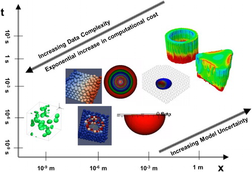
28 Hierarchical modelling approaches for AM
Recent advances in hardware capabilities have increased the power available for the heat source, while the speed of systems range from 25·4 mm s−1 for wire-fed DED21 to 3000–5000 mm s−1 for EBM.16 Faster heat source speeds have enabled almost infinite possibilities for optimising beam scan paths119 and power strategies to alleviate detrimental effects of preferential grain growth, distortion and residual stresses. Investigating this entire process parameter space by experiments is impractical, if not hopeless. Computational modelling120 empowered by the HPC and scalable tools can efficiently explore this parameter space and develop insights into the underlying physical phenomena. While it is important to relate the models to the underlying recurring physical mechanisms, there is no need to explain every relation by reducing it to the microscopic effects and models. The selection, assembly and deployment of theory and computational models are complex endeavours that will evolve with time as better physical understanding of all the processes controlling AM part quality is achieved.
An overview is now given of simulation activities at the different scales, and comments about upscaling and integration across these scales are addressed, along with the need for uncertainty quantification (UQ).
Micro-scale (10−9 m to 10−6 m): microstructure evolution under non-equilibrium conditions associated with fast heating and cooling rates
The simulations of this scale typically address the evolution of the microstructure during non-equilibrium solidification and the effect of subsequent thermal cycling encountered in a typical volume element during AM. Though this scale includes the grain structure of the AM material, modelling efforts to describe grain structure have actually been done on the beam level (10−3 m). Recent modelling efforts have focused on describing the previously mentioned CET by modelling melt pool temperature gradients and liquid–solid interface velocities through heat transfer analysis of the applied heat source (see ‘Beam level’ section). So, discussion of simulation on this scale is limited to phase evolution. Work to understand solidification segregation of alloys has used software such as JMATPRO121 and Thermocalc.117 These techniques are typically based on the Scheil equation,122 which predicts segregation of solute by
The concentration of solid frozen at the liquid–solid interface is
Solid-state phase transformation modelling117,121 may also use software like Thermocalc or JMATPRO.123 Both software are based on CALPHAD124 methodology which uses experimental and theoretical data, including Gibbs free-energy models. There are algorithms to improve modelling of multi-component systems uses the Scheil–Gulliver model for solidification and the Johnson–Mehl–Avrami equation for TTT/CCT prediction). This form of modelling allows for modelling microstructure evolution based on the cool down path. A time–temperature transformation (TTT) diagram is based on the assumption of isothermal holding and an initially uniform phase/composition distribution. A continuous-cooling-transformation (CCT) diagram is based on the assumption of a linear cool down from an initially uniform phase/composition distribution. The nature of non-equilibrium solidification, with high amounts of solute segregation in some cases, means that the modelling of phase formation for AM processes is difficult. To complete calculations further, material is added in various stages; each layer has a potentially unique thermal history (more time in the machine for the first layers melted/deposited). These unique thermal histories must also allow phase dissolution to be accounted for (currently not done in TTT/CCT models).116 The application of CCT phase prediction was addressed in recent work,117 but various assumptions are required and make analysis difficult (see Fig. 29).
The metallurgy and processing science of metal additive manufacturing
Published online:
07 March 201629 Work in EBM IN718 explored the use of CCT diagrams to explain phase formation, discussing the various assumptions that must be made to account for the thermal history of the part117
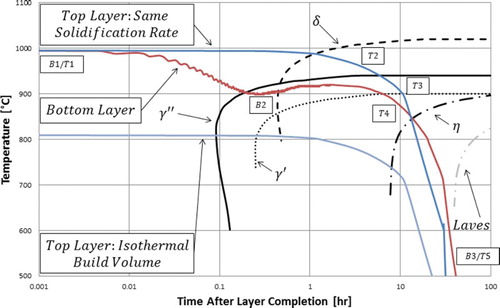
29 Work in EBM IN718 explored the use of CCT diagrams to explain phase formation, discussing the various assumptions that must be made to account for the thermal history of the part117
Given the extreme thermo-mechanical history experienced by typical volume elements, it is clear that a truly predictive microstructure evolution model should be based on a multi-physics, multi-scale approach. Because of the rapid heating and cooling cycles involved, meso-scale techniques need to be able to efficiently couple time-dependent heat, mass and interfacial fluxes within the simulation volume, especially for solid–liquid transformations. The phase-field technique that does not require explicit tracking of the interface is ideally suited for simulating such a solidification process. One of the possible approaches is suggested by Ramirez and Beckermann125 where they use the conventional free-energy-based formulation and solve the Ginzburg–Landau equation to evolve the non-conserved phase-field parameter and the Cahn–Hilliard equation to solve both thermal and solute diffusion in a coupled fashion.
Recently, Radhakrishnan et al.126 have performed large-scale phase-field simulations (with high spatial resolution, incorporating energy contributions due to thermodynamics, interfacial and strain energies) to demonstrate the evolution of multiple variants of alpha in Ti–6Al–4V under laser additive manufacturing conditions. They also show that it is possible under certain thermal conditions to straddle the alpha to beta transformations, leading to mixed colony/basket-weave microstructure. The advantage of such simulations is to predict the local microstructure as a function of local temperature profiles (derived from the macro-scale) and the ability to upscale information about mechanical properties for macro-scale simulations. Recent work in Inconel 718 has demonstrated similar phase-field modelling capabilities,127 but has yet to be applied to AM conditions.
Particle-scale (10−6 m to 10−3 m): simulations of particle interactions
Particle level simulations use intrinsic bulk properties of the materials and effectively simulate the detailed physics of beam interaction with the powder. Heat transfer processes within the powder beds can be used to model the system accurately over small regions of interest. These simulation results can then be used to obtain correlations needed for continuum simulations.
Work by Korner et al.77,89 has explored the use of a 2D-lattice Boltzmann model to simulate consolidation mechanisms for PBF and the transformation of individual powder particles into dense material (Fig. 30). Dominant physical mechanisms were identified and incorporated into the model (absorption, melting/solidification, convection, heat conduction, wetting/dewetting, capillary forces, gravity and powder layer), while secondary mechanisms were neglected (vapourisation, solidification shrinkage, radiation, sintering and Maragoni-convection). The model is specific to PBF processes, and it is noted that the neglect of radiation, vapourisation and Maragoni-convection for EBM will be addressed in future work (these terms are important to the near-vacuum, EBM process).
The metallurgy and processing science of metal additive manufacturing
Published online:
07 March 201630 The application of a 2D-lattice Boltzmann model demonstrates the simulation of powder consolidation (melting of powder, solidification as a dense solid)77
30 The application of a 2D-lattice Boltzmann model demonstrates the simulation of powder consolidation (melting of powder, solidification as a dense solid)77
Recently, Moser et al.128 have used the discrete element method (equivalent to molecular dynamics for granular material) and obtained effective properties for thermal conductivity, absorptivity and penetration. Researchers at LLNL have used an Arbitrary Lagrangian and Eulerian methodology in ALE3D simulation software to solve particle scale melting and solidification.76,129,130 In general, these simulations are computationally expensive and for the conditions relevant to the macro-scale, one needs to perform targeted particle scale simulations to extract homogenised properties.
Meso-scale (10−3 m): phase change dynamics and fluid flow at the beam level
At this scale, the main emphasis is on simulating continuum dynamics for melting and solidification. The molten material is assumed to behave as a Newtonian fluid, and is under incompressible, laminar flow.131 The interdendritic flow in the mushy zone can be modelled as a Newtonian flow in permeable media. The model formulation is based on continuum mass, momentum and energy conservation equations. The continuum properties (e.g. density, velocity, enthalpy and thermal conductivity) are based on weighted volumetric fractions of the phase constituents. The model can also include surface tension and tracking of the free surfaces based on the volume of fluid, level set or other front tracking methods.
Recently, ORNL researchers have used a parallel open-source code Truchas132 that uses finite volume discretisation of the governing equations. The role of scan strategy, or path sequencing, on the melt pool shape has been explored133 and also the variation of G/R for spot melting with EBM (with 50 μm beam diameter) of Inconel alloy has been studied.134 These simulations explicitly track the phase change dynamics and with the mesh resolution requirements as well as small time steps needed to resolve the relevant physics, are surely suitable for simulations over few layers and small regions. The effective phase change dynamics can be encapsulated as correlations that can be used in the macro-scale thermo-mechanical simulations. There has been significant work in the recent years from the groups of Profs. DebRoy135 and Stucker136 in modelling the thermal transport and fluid flow at the beam scale. The former group uses a static (but refined) meshed to capture the evolution of the melt pool, while the latter group has developed an adaptive mesh algorithm to reduce the computational cost, as one needs very fine mesh in the vicinity of the beam. These simulations are able to provide melt shape, temperature within the melt, G/R ratios, cooling rates, etc. as a function of operating conditions, and, so far, the validation is mostly qualitative in nature.
Macro-scale (10−3 m to 1 m): thermomechanics of granular, mushy and solid regions
The final aspect in this simulation hierarchy is to develop methods for simulation of thermo-mechanical behaviour in granular, mushy and solid regions. Continuum models that describe AM processes can reduce the experimental parameter space but require homogenised properties such as effective thermal conductivity, beam absorptivity, beam penetration profile, etc. The heat source, the corresponding phase change (liquid, solid and powder) in the macro-scale, temperature distribution, and the resultant macro-scale stresses and strains have to be modelled accurately to determine the effect of the processing and material properties on the eventual mechanical and geometrical performance of the part. Thermo-mechanical simulations should address principal phenomena of interest such as the development of residual stresses,92,137 distortion138 and formation of cracks.92,138
Hodge et al.139 have performed thermo-mechanical simulations of the SLM process using the Diablo code and coarse-grained approximations of the phase change dynamics while accounting for the mechanical stresses. This work notes that the Bathe algorithm for calculating phase changes is computationally intensive, and further work is proposed to improve the efficiency of this calculation. Recent work by Prabhakar et al.91 has explored the effect of thermo-mechanical cycles during EBM on substrate warping and residual stress using finite element analysis (FEA) software ABAQUS (see Fig. 31). Here, additional coarse-graining has been performed to lump several successive layers and, surprisingly, one can approximate 10–20 layers as one for these macroscopic simulations. In general, the simulations provide qualitative and semi-quantitative agreement with the experiments and are useful in conjunction with experiments. However, the state of modelling is not at a point where predictions can be made for a new system where one could build a part in one go based on modelling results.
The metallurgy and processing science of metal additive manufacturing
Published online:
07 March 201631 FEA modelling of substrate warping during processing used simplified temperature input assumptions to quantify displacement at various stages of processing in EBM of IN71891
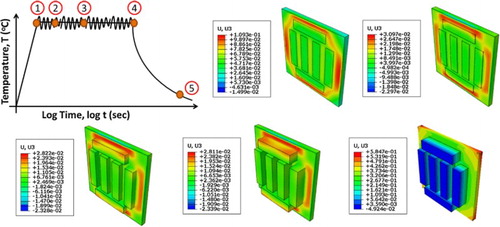
31 FEA modelling of substrate warping during processing used simplified temperature input assumptions to quantify displacement at various stages of processing in EBM of IN71891
Future modelling and simulations directions
Uncertainty quantification and optimisation
As calculations are coupled across the scales shown in Fig. 28, there will be an increasing need to understand and quantify how error propagates between computations in AM simulations. Detailed UQ of various physical and processing properties is needed to understand the most dominant properties determining the quality of the parts, as well as to predict part properties with error bars. Such an effort will be useful for in silico optimisation of AM processes for improving part properties at reduced costs by reducing the number of trial and error (‘cook and look’) experiments needed to develop effective process parameters and conditions.
Upscaling methods
As mentioned earlier, the AM processes span a large range of length and timescales. In order to have successful simulation capability, one needs to couple models across scales (continuum, meso-scale and atomistic) and physics (e.g. phase change processes and thermomechanics). This can be done by the offline tabulation of data and correlations to couple across the various scales and physics. The atomistic and meso-scale simulations will provide tabulated data in terms of thermo-physical and thermo-mechanical properties as a function of local point properties as well as gradients (where necessary). The phase change dynamics will provide thermo-physical properties as a function of local temperature, volume fraction, volume fraction gradients, spatial and temporal gradients of temperature. All these properties can be accessed by the thermo-mechanical simulations to have accurate predictions of AM part distortion (warping due to stress relief), residual stresses and mechanical performance.
Post-processing
When metal comes out of an AM process, there are many steps that are typically used to prepare an as-fabricated part into an end-use part; parts are not ready for most end-use applications directly out of a machine. Excess powder must be removed, parts must be removed from the build substrate, support structures must be removed, thermal treatments may be required to improve mechanical properties, and the surface of parts must be finished to achieve the desired surface finish and geometrical tolerance.
Powder, support, & substrate removal
After a part is fabricated, excess powder, support structures and substrate material must be removed. Powder-bed processes require powder to either be vacuumed from the part if loose (SLM) or blasted off using loose, similar powder if sintered (EBM). DED processes may require machine cleanup, but the finished parts are not encased in feedstock. Support structures, for mechanical and thermal support, are frequently used in PBF and must be mechanically removed by application of force or cutting. The build substrate is typically adhered or joined to the finished part and must be cut off using a saw or wire electrical discharge machining. The interface of stainless steel substrate and Ti–6Al–4V is an exception in that parts may be fractured off the substrate by application of force (typical in EBM production of Ti–6Al–4V).
Thermal post-processing
After parts are removed from the substrate and support material, thermal post-processing may be used to relieve residual stress, close pores and/or improve the mechanical performance of the material. As-fabricated metals typically require heat treatment to achieve the desired microstructure and mechanical properties required for service. Material may be treated by HIP to reduce porosity and internal cracks, furnace heating to solution treat and/or furnace heating to age. Standard treatments for the commonly processed materials Ti–6Al–4V and IN718 are given in Table 3. The various treatment options can effect changes in grain size, grain orientation, precipitate phases, porosity and mechanical properties. Heating AM metal in a furnace to effect changes in microstructure is the general goal of thermal post-processing. Thermal post-processing of metal affects grains through recovery, recrystallisation and growth. Microstructure evolution is modified by dissolution, precipitation and growth.
The metallurgy and processing science of metal additive manufacturing
Published online:
07 March 2016Table 3 Common post-processing procedures for Ti–6Al–4V and Inconel 718
Stress relief
Stress relief involves recovery; atomic diffusion increases at elevated temperatures, and atoms in regions of high stress can move to regions of lower stress, which results in the relief of internal strain energy. SLM and DED parts are typically annealed to remove residual stress (see Fig. 32), commonly prior to removal from the substrate. Stress relief treatments must be performed at a high enough temperature to allow atomic mobility but remain short enough in time to suppress grain recrystallisation (unless desired) and growth (which is usually associated with a loss of strength). Recrystallisation may be desirable in metal AM to promote the formation of equiaxed microstructure from columnar microstructure. This has been observed in SLM iron, where it was theorised that thermal residual stress acts as the driving force (in the absence of cold working) for observed recrystallisation.100 Similar phenomena have been noted in wire-fed DED Ti–6Al–4V.140,141
The metallurgy and processing science of metal additive manufacturing
Published online:
07 March 201632 Stress relief through vacuum annealing can almost eliminate residual stress100
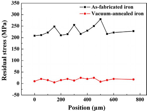
32 Stress relief through vacuum annealing can almost eliminate residual stress100
Recrystallisation
One of the most important effects of post-processing is on the grain structure of the processed material. As-fabricated metal AM parts typically have a columnar, oriented microstructure (especially in PBF), though heat treatments may alter this microstructure. Research on SLM100 and DED140,141 has noted recrystallisation of as-fabricated microstructure during annealing (no HIP). In the materials in these studies (iron and Ti–6Al–4V), residual stress is proposed as a likely driving force for this recrystallisation (RX). In SLM of IN718, partial recrystallisation occurred during stress relief annealing (Fig. 33) and led to a very heterogeneous grain structure.142
The metallurgy and processing science of metal additive manufacturing
Published online:
07 March 201633 Recrystallisation of SLM IN718 during stress relief produces an inhomogeneous grain structure142
33 Recrystallisation of SLM IN718 during stress relief produces an inhomogeneous grain structure142
RX in DED materials has been reported for both wire-fed and powder-fed systems, with residual stress as the likely mechanism. Brandl et al.140,141 explored solution treatment (ST) of DED Ti–6Al–4V and noted that RX occurred without hot or cold work. Furthermore, it was noted that the RX resulted in a grain structure change from columnar to globular, though the resulting RX grain size could not be controlled and resulted in coarse grains (300–400 μm). In DED of IN718, Cao et al.143 observed non-uniform RX with different grain morphology from the original columnar structure. It was observed that overlap rate significantly influenced residual stress and the location of RX nucleation. RX grains tended to be relatively fine, though the RX process did not completely eliminate the prior columnar grains. Blackwell reported smaller amounts of grain growth from HIP of DED IN718 in deposited material than in the attached substrate of the same material.144 The cause of this is not known, although it is speculated that carbides or oxide may not have been dissolved by the 1160°C HIP cycle and acted to produce Zener pinning in the as-fabricated material. Zhao et al. noted recrystallisation at various axial locations in DED IN718 after homogenisation at 1080°C, likely due to residual stress.53 Variance in local Niobium concentration has been observed to result in grain growth in Nb-poor regions during heat treatment of DED IN718.54 This is due to a lower δ-solvus in regions of lower Nb concentration.
In EBM, RX is not typical during heat treatment of Ti–6Al–4V, but has been observed to occur in IN625 and IN718. Facchini et al.145 studied anneals on deformed and un-deformed EBM Ti–6Al–4V. It was found that increasing strains led to the formation of globular RX, whereas less strained or unstrained regions retained the as-fabricated lamellar structures. The driving force in this case was shown to be deformation from mechanical testing. However, Murr et al.146 noted RX of EBM IN625 in un-deformed material. It has been shown that residual stress is greatly reduced in EBM compared with SLM,95 so residual stress is not a likely driving force for RX. In fact, others have reported a similar phenomenon in EBM of IN718 for some STs147 and HIP.148 It is not clear that RX precedes the observed grain growth in these cases, and more work to understand grain growth mechanisms in AM material is needed. Others have reported no RX in EBM IN718 and even noted that heat-treated grains become even more oriented.149 None of this work has proposed mechanisms for the RX or grain growth noted, and the cases in which this RX or grain growth occurs are not understood.
Hot isostatic pressing (HIP)
HIP can be used to close internal pores and cracks in metal AM parts. Internal pores, or ‘closed’ pores, are surrounded by material in the centre of the sample. When pores form at the surface, they are considered ‘open’ pores. Open pores caused by surface defects are a problem for post-processing, as they allow deeper infiltration into material from air during high heat cycles, as shown in Fig. 35. Internal cracks may also be closed by HIP, as has been shown in SLM nickel-based superalloy parts.82 The use of HIP may significantly alter the grain structure of AM parts. Standard HIP cycles may yield very large grains, as published in recent work on EBM of Inconel 718.148 There is also evidence that AM material responds differently to HIP than traditional material; LENS Inconel 718 was deposited on Inconel 718 substrate and characterised before and after HIP, and it was noted that grain growth occurred in the substrate during HIP but not the deposited material, possibly due to carbides or other high-temperature phases not dissolved during HIP.144 This means that characterisation of as-built microstructure is critical to applying the correct HIP post-processing of AM parts. Alternatively, the homogenisation of AM alloys prior to HIP or other post-processing could lead to standard post-processing procedures that are independent of processing conditions. Most post-processing of AM parts is currently performed this way, but the use of standard wrought or cast post-processing procedures may not be ideal for AM-processed alloys.
ST & aging
For precipitate hardened materials (like Inconel 718), an ST can be used to dissolve unwanted phases and aging can be used to form and grow precipitate phases. Sometimes, these processes are performed sequentially and referred to as solution treated and aged (STA). The ST temperature should be selected above the solvus temperature at which all undesired phases will dissolve. The ST time should be long enough to dissolve precipitates but short enough to limit grain growth. After a material is solutionised to form a solid solution, the matrix of the material is essentially ‘reset’. Aging can now be done on the reset material, without the need to consider prior phase structure. The purpose of aging is to precipitate harden a material. These steps are common for cast and wrought materials, and have been performed on AM material.142,147,148,150
Surface finishing
AM parts bound for service are typically machined to achieve a smooth surface finish. As-fabricated parts typically have high surface roughness, the origins of which have been discussed previously. The most common way to machine the near-net shapes or parts produced using AM is to use CNC mills associated with subtractive manufacturing. Simple rotary-tool polishing or grinding with a belt sander (flat surfaces) may be adequate for some applications, but do not typically meet the standards required for high-quality parts. Chemical polishing has been explored on mesh structures and future work on electrochemical polishing is recommended.151
Parts to be used in service typically undergo thermal post-processing, which can oxidise the surface of the metal. Post-HIP parts are shown in Fig. 34, before and after surface machining.152 If open pores are present, oxidation can extend into the interior of the part as shown for thin-wall EBM samples in Fig. 35. Defects like this can be, and must be, avoided because they may not get removed by surface machining. CNC of freeform surfaces has been extensively reviewed in relation to tool path selection, tool orientation and tool geometry.153
The metallurgy and processing science of metal additive manufacturing
Published online:
07 March 201634 Post-HIP Ti–6Al–4V brackets, before (top) and after (bottom) machining (reprinted with permission)152
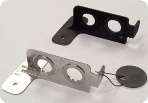
34 Post-HIP Ti–6Al–4V brackets, before (top) and after (bottom) machining (reprinted with permission)152
The metallurgy and processing science of metal additive manufacturing
Published online:
07 March 201635 Thin-wall EBM fracture surface of Inconel 718 from post-HIP sample with notable change in surface oxidation and oxidation of an open pore caused by lack-of-fusion near the edge
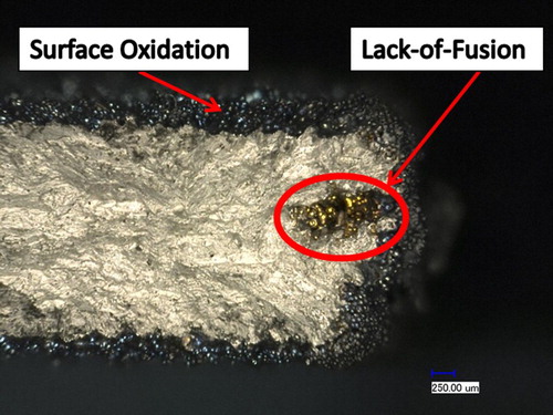
35 Thin-wall EBM fracture surface of Inconel 718 from post-HIP sample with notable change in surface oxidation and oxidation of an open pore caused by lack-of-fusion near the edge
AM and CNC have been explored for operation in tandem,154 which is commonly referred to as ‘Hybrid manufacturing’ or ‘Hybrid AM’. Hybrid systems typically pair a DED process with CNC, using the same mounting position to position the CNC tools. This type of hybrid process is currently in use for part repair of aerospace components, capable of repairing compressor blades and other complex service parts.155 Turbine blade repair using this method is shown in Fig. 36. Recently, a hybrid system pairing SLM with CNC called LUMEX was developed by Matsuura in Japan,156 which works by machining select features after each layer. The LUMEX process has found a niche in tool and die production, as opposed to part repair work.
The metallurgy and processing science of metal additive manufacturing
Published online:
07 March 201636 Airfoil repair using a hybrid DED+CNC method155
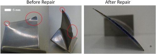
36 Airfoil repair using a hybrid DED+CNC method155
New materials development
The feedstock for metal AM processing must meet some general requirements. It must be in a powder, wire or sheet form and must be machine compatible (e.g. exposable to air, electrically conductive, etc.). A wide range of candidate materials meet these broad requirements, although current AM hardware makes the fabrication of parts from oxidation-prone materials difficult (powder is frequently loaded in open air). There are currently a limited number of commercially available alloys for AM. A handful more have been researched, but there remains tremendous opportunity in processing new material and in developing new alloys specifically for AM.
For powder feedstock, the initial powder composition is very important in determining the chemistry of final parts; any pick-up of oxygen or loss of metals to vapourisation must be accounted for. Powders can be either PA or mixtures. PA powder is produced from a feedstock (ingot, bar, etc.) of the desired alloy. Mixtures are made by mixing powders of different chemistries together as shown in Fig. 37, forming the final alloy during the AM melting process. Mixtures of elemental powders are common in the PM field and are termed blended elemental. Pre-alloyed (or ‘PA’ in PM) powders are the most common, although work has been done to demonstrate processing of mixtures.157
The metallurgy and processing science of metal additive manufacturing
Published online:
07 March 201637 Ti-6Al-4V-ELI, extra low interstitial, (large, round particles) mixed with 10 wt-% Mo (white, irregular particles). Powder mixture was processed using SLM, which led to room temperature
37 Ti-6Al-4V-ELI, extra low interstitial, (large, round particles) mixed with 10 wt-% Mo (white, irregular particles). Powder mixture was processed using SLM, which led to room temperature
Some currently available commercial materials and previously researched materials for AM are summarised in Table 4. The commercially available materials are mostly steels, stainless steels, structural aerospace material (Ti–6Al–4V), bio-compatible implant materials (Ti, Ti–6Al–4V, CoCr) and high-temperature materials (Inconel 626, Inconel 718, CoCr). Promising research has been done on refractory materials (Ta, W-Ni, Nb). Bulk amorphous metallic glasses have also been demonstrated (see Fig. 38),158 but little information is available, presumably due to proprietary considerations (e.g. a recent patent by Apple Inc.).159 Sheet Lamination has the potential to join many dissimilar metals through ultrasonic joining (Fig. 39). DED research is developing hydrogen storage materials,160,161 ceramics162 and WC.163 The high energy of some DED systems allows for melting of some of these exotic materials. Binder Jetting has only recently demonstrated pure alloys (IN625), but more research is expected to be seen in this area. Pure alloys and ceramic materials both have significant development work to be done in understanding the consolidation/sintering process to produce fully dense parts using Binder Jetting.
The metallurgy and processing science of metal additive manufacturing
Published online:
07 March 2016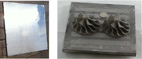
38 (Left) Bulk metallic glass made in EBM, with amorphous structure158 and (right) EBM-fabricated Al 2024 impellers on build substrate73
The metallurgy and processing science of metal additive manufacturing
Published online:
07 March 201639 Tabular representation of alloys that can be joined using ultrasonic consolidation257
39 Tabular representation of alloys that can be joined using ultrasonic consolidation257
The metallurgy and processing science of metal additive manufacturing
Published online:
07 March 2016Table 4 There is a limited scope of currently available commercial materials, but there are ongoing R&D efforts in materials development
Recent alloy development has focused on alloy systems that have uses in high impact industries (e.g. titanium alloys and nickel-based super alloys). While this trend will likely continue, more emphasis is expected for alloy design specifically for AM processes. Alloys designed for AM would potentially accommodate large thermal gradients during solidification and facilitate the control of (1) columnar or equiaxed grain formation, (2) orientation and (3) in situ phase precipitation. While development of new alloy compositions for AM processes is yet to be realised, some researchers have experimented with additives to existing alloys; an example of this is the use of boron to control β-grain growth in EBM Ti–6Al–4V.164
Microstructure and mechanical properties
Characterising the microstructure and mechanical properties of PBF and DED materials is a critical component of any AM development programme. Grain morphology, grain texture and phase identification are typically accomplished via light optical microscope (LOM), SEM, electron backscatter diffraction (EBSD), X-ray diffraction (XRD) or some combination thereof. Tensile properties and hardness are the most commonly reported and measured mechanical properties, although some studies of fatigue life and creep have been completed. To discuss the importance of microstructure and mechanical properties, it is expedient to focus on two different alloy systems, Ti–6Al–4V and Inconel 718, as there is much published research on PBF of these alloys.
Microstructure
The microstructure of AM produced metals has unique properties. Columnar grain structure dominates, with high amounts of grain orientation. Phase formation is process and material specific. Axial variation of grains and phases may occur due to subsequent heating and cooling cycles of the material. The scan strategy can be used to control the microstructure in theory (G vs. R),165,166 and recent results show significant progress towards demonstrating control. Porosity is a concern with all processes, though <1% porosity can be achieved using DED, SLM or EBM by optimising process parameters.
Grain structure
Grain structure in AM alloys is dominated by highly oriented, columnar grains. These structures are common in Ti–6Al–4V produced by EBM,167 SLM168 and DED,141,169,170 as well as Inconel 718 produced by EBM,16,148 SLM95,142,171 and DED.172 Columnar grain structure develops because of the melt pool geometry (can be related to G vs. R, as previously discussed) and heat flow in the melt pool. DED grain structure is not always as oriented or columnar as SLM or EBM. In fact, DED grain structure is highly influenced by the nature of the scan strategy, as shown in Fig. 40.172 These results show some difference based on the scan strategy, but the most pronounced difference is with higher energy melting. The resulting larger, more columnar grains should be expected; more applied energy means a larger and deeper melt pool. This will include more layers during remelting, which should promote epitaxial grain growth and a more oriented microstructure (as observed). This result can be extrapolated to other systems, given knowledge of the power per area [W mm−1 s−2].
The metallurgy and processing science of metal additive manufacturing
Published online:
07 March 201640 Grain structure in DED material is highly influenced by scan strategy. Shown is Inconel 718, produced using a unidirectional, b, bi-directional and c bi-directional, high power scanning172
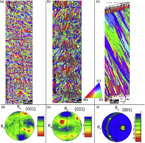
40 Grain structure in DED material is highly influenced by scan strategy. Shown is Inconel 718, produced using a unidirectional, b, bi-directional and c bi-directional, high power scanning172
Discussed in more detail later, EBM and SLM have much higher power per area capabilities than DED systems. This has a direct impact on the amount of remelting and epitaxial growth. The large layer thickness of DED makes finer control of microstructure difficult due to a larger minimum feature size. In some cases DED processes have been used to promote epitaxial growth of single crystal material,173 where the top layer (which may exhibit some spurious grain growth) can be removed in a hybrid process.
In SLM, the typical scan strategy used (island scanning) has evolved to reduce residual stress and cracking. The island scanning technique has recently been noted to cause repeating patterns in grain orientations.114 This differs significantly from the oriented columnar structure seen using a rectilinear raster (no islands). Depending on the desired grain structure, this may be a limitation. In general, residual stress impacts grain structure from the standpoint of the scan strategies used to avoid it or as a driving force for heterogeneous recrystallisation.
In EBM, very high (001) orientation in the build direction is normal in both Ti–6Al–4V and Inconel 718. Work to study the origins of this texture observed the effect of grain nucleation from powder particles.174 Additionally, this work demonstrated a clear distinction between the fine grained, equiaxed microstructure of the contour region and the highly oriented, bulk melt. Grain size and orientation has also been noted to vary from the edge to the centre of a melt pool,175 which agrees with common knowledge from welding and casting. Grain nucleation can occur at edges from powder particles in PBF (Fig. 41), which can result in increased misorientation near edges or in thin walled structures.
The metallurgy and processing science of metal additive manufacturing
Published online:
07 March 201641 Effect of powder and edges on grain growth in EBM Ti–6Al–4V174
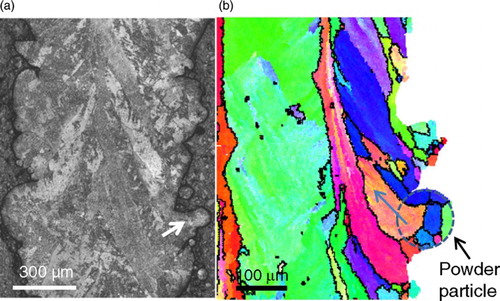
41 Effect of powder and edges on grain growth in EBM Ti–6Al–4V174
Phase formation
Phase formation during solidification and solid-state phase transformation during cyclic process heating have been studied for DED116,121 and EBM.117 Phases that form during rapid solidification of the melt material may coarsen and/or dissolve during subsequent passes of the heat source. This effect was discussed previously and is shown in Fig. 26. DED of IN718 has been noted to form non-equilibrium Laves eutectic heterogeneities that transform into δ-needles during ST (ST should reset the phase structure).54 Such needles are typically associated with over-aging. Such solidification Laves formations have been reported in SLM but not EBM. In EBM, the powder-bed temperature used for processing was shown to directly impact the width of α-phase grains, or laths, in Ti–6Al–4V and, correspondingly, tensile properties.167 Furthermore, axial variation of lath width in Ti–6Al–4V has been noted in EBM.176 The higher powder-bed temperatures (400–1000°C) of EBM are unique, and similar effects are not noted in the lower bulk temperatures (20–200°C) of SLM or DED processing.
Microstructure control
Local control of microstructure is possible with metal AM processes, and recent research is just beginning to demonstrate the possibilities. PBF processes have produced especially interesting results due to the accuracy and the speed of lasers and e-beams. Manipulation of G vs. R (see previous section on thermal history) has been known to modify grain structure of material during traditional processing, and applies to AM processes through manipulation of scan strategy. Control of microstructure can be discussed with respect to either grains or phases.
Control of grain morphology and size can be achieved through manipulation of G vs. R. While G vs. R curves may predict mixed grain morphology, it has been difficult to produce experimentally. It is speculated that this is due to a preference toward columnar growth once it has been established.167 Many papers have addressed the benefits of controlled grain structure,112,177 but demonstration has not occurred until recently in DED172 and EBM.178,179 Beam modulation in wire-fed, electron beam DED has shown that beam modulation (rapid variance of the beam power) can be used to produce finer grain structure.180 This alternative method causes a dynamic melt pool due to a rapidly changing heat flux. The clearest demonstration of local control of grain orientation was achieved using EBM of IN718 to embed the letters D-O-E (stands for the sponsor of the research, the ‘Department of Energy’) in misoriented grains within a highly oriented matrix (Fig. 42 shows this visually using an inverse pole figure representation from EBSD).181
The metallurgy and processing science of metal additive manufacturing
Published online:
07 March 201642 Local control of grain orientation in EBM of IN718 (used with permission)181
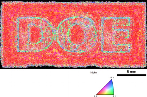
42 Local control of grain orientation in EBM of IN718 (used with permission)181
Phase control is more complex, as formation can be influenced by solidification and solid-state phase transformation. Previous work in AM has investigated microstructure control of precipitate phases during fabrication by varying process parameters. For example, during SLM of Ti–6Al–4V it was found that precipitation of Ti3Al could be controlled by varying solidification rate through scanning speed.182 The segregation of aluminium during rapid solidification leads to periodic fluctuations of aluminium content, which is identified as a driving force for Ti3Al precipitation. While this precipitation may not directly occur due to solidification, the non-equilibrium phase formations have a short time-scale for formation during either solidification or subsequent beam passes (order of seconds to minutes in SLM). Other work on low-purity copper notes the possibility of microstructure control of Cu2O but does not demonstrate active material control.183 Both these examples control phase formation through solidification control (control of the beam speed, beam power or scan strategy). This approach, however, faces an inherent limitation in that process parameters affect both matrix solidification grain structure and precipitate evolution, potentially forcing the optimisation of one characteristic at the expense of the other. Solidification structures are affected by subsequent heat source passes (as discussed previously). Recent work has rationalised solid-state phase transformation in DED121 and EBM.117 Solid-state phase transformation can amount to in situ aging of material. In DED, this is done on subsequent beam passes. In EBM, subsequent passes and holding at elevated temperature cause this change. The complex thermal histories present have allowed researchers to rationalise phase formations due to solid-state phase transformation, but more work is needed to be able to predict microstructures. No work in metal has yet truly demonstrated process control of precipitate formations via solidification or solid-state phase transformation to produce desirable phase structures.
Mechanical properties
The mechanical properties and performance of AM material is still being measured and understood. Much of the literature on AM focuses on mechanical properties, specifically tensile behaviour and hardness. Tensile tests to measure YS, UTS and elongation are the most commonly used tests to compare AM mechanical properties to traditionally processed materials (cast and wrought). The location and orientation from which mechanical testing samples are taken from builds is important and should always be reported with results. ASTM standards exist, but are typically process and alloy specific. Defects, such as porosity, that affect mechanical properties may influence the test results of as-fabricated material but can typically be eliminated or reduced by post-processing.
Porosity, residual stress, test specimen orientation and thermal history are particularly important factors to consider when discussing mechanical test results of AM materials. Unfortunately, not all reported research includes these necessary details. Orientation of the build direction relative to the test direction, quality and production method of feedstock, void fraction of porosity, thermal history during processing and post-processing thermal history should all be included with any test results. This section focuses on mechanical properties of bulk material (as opposed to mesh or foam structures).
Porosity has been observed to reduce hardness in SLM of stainless steel 316L.184 It was observed that porosity from entrapped gas pores led to a small number of early fatigue failures in wire-fed DED of Ti–6Al–4V.185 Porosity can negatively affect mechanical properties in welding due to a reduction in cross-sectional area.186 Aligned pores (non-random) or pores with sharp edges in this case were found to be more detrimental than homogeneously dispersed spherical pores. The effect of porosity on tensile properties in welding is most notable in the reduction of elongation.187
Different machines may have very different thermal histories of material, which may manifest in as-fabricated mechanical properties as variance in hardening through coarsening or aging. Similarly, the details of any post-processing heat treatments are equally important in determining mechanical properties. Data for many AM processes is only given in the stress-relieved or heat-treated states, which tend to have better mechanical properties. As a result, the amount of published data on as-fabricated samples (samples as they come out of the machine) is sparse. Previous work has compiled some mechanical properties, focusing on Ti–6Al–4V and Inconel 718/625.79 A summary of tensile properties for DED, SLM and EBM is presented in Table 5 for Ti–6Al–4V and Inconel 718.
The metallurgy and processing science of metal additive manufacturing
Published online:
07 March 2016Table 5. Compilation of reported tensile results for Ti–6Al–4V and Inconel 718
When as-fabricated samples are tested, the geometry of test specimens, surface finish and type of measurement (global vs. extensometer) can all have a significant impact on resulting data. Comparisons of such data must therefore consider testing methodology. Sample geometry, as discussed previously, can impact local heat transfer conditions, which can impact solidification, defects and microstructure. It is therefore important to know how the parts were built (including what other parts they were built with) to determine the complete build geometry.
For the use of as-fabricated material (not machined), surface finish is typically poor compared to well-polished test specimens. Rough surface finish can introduce stress risers or crack nucleation sites at surface defects or flaws. Using parts straight out of the machine may negatively affect fatigue performance.168 This work notes that the presence of rough surfaces, residual stress and porosity can make it difficult to determine the exact reason for failure (all are known to have potential negative impact on fatigue performance). It has been observed in High Cycle Fatigue testing of SLM Ti–6Al–4V that sample polishing (polishing the surface of the gauge section) can significantly improve the cycles to failure for a given maximum stress.188 The as-fabricated, un-polished samples show crack initiation at the rough surfaces of the part, whereas polished parts show mixed failure modes (some internal, some initiating as the surface). Other work to compare mechanical performance between SLM Ti–6Al–4V and 15-5PH stainless steel has shown that surface finish can even affect fatigue performance of PH1 steels (surface initiation of fatigue cracks).189 This work also shows that tensile fracture in SLM 15-5PH was noted to be influenced by coalescence of micro-cracks and micro-voids (though this work is not necessarily a comment on the relative impact of as-fabricated surface finish, as surface condition of tensile and fatigue samples was not explicitly reported).
The reported values of UTS, YS and elongation tend to be very similar in the X–Y vs. Z-directions, with the X–Y results being slightly better in some cases (see Table 5). This is unexpected, as tensile properties of directionally solidified material (columns oriented along the Z-direction) should be superior to those in the X–Y-direction. To understand why this is unexpected, the effect of grain orientation on mechanical properties must be considered. In nickel-based superalloys, directionally solidified material is highly oriented with the100 direction. This high orientation is typically associated with an increase in primary creep resistance, rupture life and ductility performance.190 The unexpected results in many AM tests may be related to others defects (porosity, residual stress and surface finish).168 Similar columnar grain structure is seen in most metal AM parts (not just the nickel-based ones), but the increase in performance (in elongation, since orientation-dependent creep data are not as common in the AM literature) is not seen. In fact, the opposite effect is seen in AM; elongation is less in the oriented100 direction. This effect is notably seen in EBM Ti–6Al–4V, where UTS and YS remain unaffected by orientation, but elongation is 30% higher in the X–Y direction.191 For this specific case, it was noted that the effect of ‘thermal mass’ or in situ aging may have influenced results. In fact, in situ aging in EBM has been noted to influence mechanical properties in IN718 as well.16,117 Depending on the material, the effect of aging appears to more strongly influence mechanical properties than the orientation of the material. EBM is unique in this in situ aging, and such an explanation cannot be applied to similar orientation variation in DED and SLM processing. In fact, the underlying mechanism for the unexpected mechanical performance due to orientation variation has not been well studied or identified for DED or SLM.
Post-processing can improve mechanical properties, but must be applied correctly for a given starting microstructure. The starting microstructure can vary based on process parameters (which may impact solidification kinetics), which may cause need for non-standard post-processing. Having to determine a post-processing procedure for each batch is not ideal or feasible. Work must be done to characterise the range of microstructures that may form for a given material in a given machine. If a treatment can be applied across this variance in microstructure with acceptable results, then it can be applied uniformly. If not, then processing windows must be set to insure quality control on the material coming out of the machine. For processes without in situ aging (LM, DED), processing parameters mostly impact solidification microstructure. For EBM, which undergoes in situ aging, variable amounts of aging may lead to issues in ST.117 Processing windows for EBM or precipitate hardened materials must therefore include process parameters that determine solidification kinetics and the size of the part (how long it will hold in the machine). Standard post-processing with HIP will typically change tensile properties (elongation may improve at the expense of UTS/YS in precipitate hardened materials), but can close pores (should improve fatigue life).
Recent work has focused on development of standardised testing procedures for AM processes. ASTM standards have been developed for PBF Ti–6Al–4V,192 Inconel 718193 and Inconel 625.194 The ASTM guidelines offer criteria for material, but allow for agreed upon specifications between the manufacturer and the end-user. For researchers, there is no official standard for reporting test results. Work by researchers at NIST using Ti–6Al–4V began efforts to develop a standardised test procedure for EBM material to account for variation of mechanical properties within the build volume191,195,196 but has yet to be written into an official standard. To improve the usefulness of published research results, authors should be diligent to report: orientation of build direction, process thermal history (if applicable), exact conditions of any post-processing and the nature of the mechanical test specimen (machined, etc.).
Outside of tensile test and hardness data, other mechanical properties of AM materials are less well studied. Fatigue and creep are of strong importance to industry for certain alloys, as they are often considered a limiting property of materials (whereas YS or UTS are not limiting for many applications of aerospace parts, for example). The most complete set of fatigue data exists for Ti–6Al–4V, with tests run on powder-fed DED,197 SLM168 and EBM.145 While differences in testing (orientation, geometry, technique, etc.) make direct comparison difficult, most as-fabricated material from DED, SLM or EBM, falls in the lower range of the performance of cast parts as shown in Fig. 43. Post-processing improves material to a level of performance comparable to annealed wrought or cast with HIP material.
The metallurgy and processing science of metal additive manufacturing
Published online:
07 March 201643 Fatigue test results of HIP and stress-relieved Ti–6Al–4V DED material197
43 Fatigue test results of HIP and stress-relieved Ti–6Al–4V DED material197
Fatigue properties may be influenced by surface finish and porosity, with samples that were processed by HIP and machined exhibiting comparable fatigue properties to wrought material.79 Machining samples (as opposed to using the as-fabricated finish) typically improves mechanical performance, but the result can be difficult to observe if material has significant porosity and residual stress.168 Efforts to understand underlying dislocation motion and model fatigue performance are limited, but have demonstrated accuracy compared to experimental results.198 Other testing of crack growth, creep,199 corrosion148 and other performance properties are also limited, making these tests a likely area of future work.
Novel methods of metal AM
Having discussed current technologies in this paper, there are some AM methods for producing metal parts that have not been as fully explored: chemical vapour deposition (CVD), physical vapour deposition (PVD), liquid metal material jetting and friction stir AM. Machine modifications to existing systems offer the chance to improve material properties, speed up deposition rates or both. Either by development of novel methods or incremental improvements to existing technology, innovation will continue to change the metal AM landscape.
PVD and CVD
Vapour deposition has been used for many decades to deposit coatings, among other applications. CVD is accomplished via a chemical reaction at the deposition surface with the particles in a vapour stream. PVD is accomplished solely through the condensation of metal vapour on the substrate and requires vacuum, whereas CVD may operate within a range of atmospheres. Though CVD and PVD are typically used for coatings, the use of CVD for metal AM has been considered using an e-beam47 or laser-jet.200,201
Cold spray
Another purely physical process is known as cold spray and is being studied for use in AM.202 Cold spray technologies typically works by acceleration of powder particles in a high-speed gas stream. This powder adheres to a substrate via plastic deformation, forming a deposit.203 Correspondingly, residual stresses in cold spray deposits are primarily due to impact and are compressive in nature. Residual stresses have not been reported for bulk deposits, which may be a significant material defect to address considering the large amount of deformation put into the deposit. The technology also appears constrained to simple, near-net shapes at present. There have been recent success stories in demonstrating cold spray techniques as shown in Fig. 44,204 and deposition rates are expected to be faster than existing metal AM processes. Though microstructures are not well characterised for cold spray processes, recent work has noted abnormalities in the precipitation kinetics of Inconel 625; typical phase precipitation was inhibited or sluggish within ranges expected to form precipitates in traditional material.205
The metallurgy and processing science of metal additive manufacturing
Published online:
07 March 201644 (Left) Operator setting up cold spray AM system, which operates outside of a controlled environment and (right) cold spray deposit forming on the tip of a substrate tube that is rotated.204 Courtesy of GE Global Research
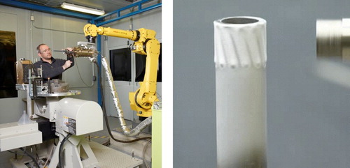
44 (Left) Operator setting up cold spray AM system, which operates outside of a controlled environment and (right) cold spray deposit forming on the tip of a substrate tube that is rotated.204 Courtesy of GE Global Research
Material jetting & other methods
Metal material jetting deposits droplets of liquid metal that either solidify upon deposition to form a part206 or remain liquid at room temperature to form arrays of liquid metal.207 Demonstration has been limited to micron-scale or smaller structures, and neither technique has been demonstrated for millimeter-scale parts. A thermal spray method for forming parts was developed in the early 1990s and employed a mask in the shape of each layer to form 3D geometries.208 This method has not seen widespread adoption since, but may provide useful methods for applying masks to generate parts in other processes. Friction stir welding has been proposed for AM,209 which operates by the method of sheet lamination. Forming of an actual part using friction stir welding has not been demonstrated either and would require pairing with CNC tools to machine of each layer of deposited material before subsequent deposits are made.
Hardware improvement and large-scale
Machine modifications to existing hardware typically support incremental improvements, but several developments could make large gains in the development of current technologies. The use of a combined feed of powder and wire for DED was demonstrated to increase deposition efficiency, improve surface finish and reduce porosity under certain conditions studied.69 The use of multiple heat sources for DED and PBF can reduce deposition times or be used to help preheat material, reducing residual stresses. In fact, new system models by SLM Solutions210 and Concept Laser211 offer combinations of 400 and 1000 W lasers in two and four laser configurations. Alternatively, multiple small power lasers have been combined to produce a cheaper power source for DED laser systems.212 Another technique is to heat the feedstock prior to deposition; wire-fed DED can be modified to heat the wire (using an arc) while creating a molten pool with a laser.213 Initial results suggest that this method can help increase deposition rate and may reduce cracking and segregation. This method may be an enabling technology for addressing one of the major limitations of metal AM: achieving large, meter-plus-scale parts.
The ability to produce large-scale, metal AM parts is limited by machine size and materials considerations. Scaling current PBF techniques to produce large-scale parts would be very expensive and require redesigning existing processes for removing and cleaning parts. Deposition rates are prohibitively slow for scaling up existing hardware processes and the cost of the powder feedstock is very high. DED processes have led the way for producing large-scale parts,24,214 but there are still limitations in producing overhangs, thick walls and other features. Polymer AM has had many of the same problems as metal AM (residual stress formation, high feedstock costs, slow deposition rates), but solutions were found215 to make a system that sacrificed resolution (surface finish) for speed and cost.216 A similar technique could be employed for metals; a specific alloy could be identified or developed that allows for open-air DED, while maintaining acceptable amounts of residual stress. Alternatively, indirect methods of manufacture could be used (such as using large-scale polymers as moulds or substrates for forming metal).
Open source and low cost
3D printing is a mainstay of the open-source hardware movement, centred on the RepRap project famous for its plastic material extrusion process. The use of open-source hardware to make research cheaper and better across a wide range of disciplines is promising.217 A major limitation of current open-source hardware is the lack of a widely used 3D metal printer. The most exciting developments in low-cost metal AM have come in the DEDcategory. Researchers at Michigan Tech University have demonstrated a stationary welder that deposits metal on top of a moving substrate (see Fig. 45). The welding machine used is a gas metal arc welding (GMAW) or metal inert gas (MIG) machine. The machine is reported to cost <$2000.218 The problem is that weld deposition has poor resolution, producing only near-net shapes. Promisingly, researchers in India have demonstrated a low-cost CNC mill to machine near-net shapes produced using a welder.154 Using a welding machine as a desktop printer may be limited due to safety issues, but the combination of open-source weld deposition with CNC milling could be an important step for open-source hardware development. PBF SLM machines capable of finer resolution may develop in the future, as related patents continue to expire.
The metallurgy and processing science of metal additive manufacturing
Published online:
07 March 201645 Open-source DED system designed with a stationary GMAW/MIG welder and moving stage/platform218
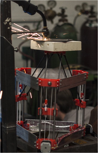
45 Open-source DED system designed with a stationary GMAW/MIG welder and moving stage/platform218
Process monitoring & quality control
Process monitoring can be used to identify the formation of defects and measure the thermal history of the material. Infra-red thermography, standard cameras, high speed video and pyrometry have all been used for in situ monitoring. Ultrasonic imaging, the Archimedes principle, X-ray computed tomography (XRCT) and neutron tomography have all been used as non-destructive means of quality control. The most common goal of defect detection is to determine the presence of porosity, although inclusions, swelling and other defects can also be detected in this manner.
Optical monitoring can yield useful data for defect identification, but IR imaging is required for temperature profiling. Images from a standard camera can be taken during powder distribution during PBF processes, but not during continuous DED processes. Standard images, and high speed videos, pick up the difference in light emission due to temperature variation. This has shown usefulness in measuring melt pool dynamics.219
To better understand solidification and thermal history, IR imaging, pyrometry and thermocouple measurement have been applied. Thermocouples can be used to effectively measure substrate temperature, but cannot be used to measure variation in part temperature or surface temperature, due to the nature of AM processes. Pyrometers have been used in DED,56 EBM220 and SLM.221 The details of the sample location of the pyrometer are important to note, as the heat source may or may not pass in the measured area, depending on part geometry. For full layer thermal analysis, IR or near-IR imaging must be used and is very important in understanding metal AM metallurgy.222 IR imaging is particularly useful for EBM, as it can be used to measure the elevated surface temperature or the powder-bed temperature as shown in Fig. 46.220 Process corrections using the average temperature from near-IR have been tested in a feedback system that adjusts process parameters during the build.176 Differences in emissivity between powder and the melted part must be taken into account, among other details.118
The metallurgy and processing science of metal additive manufacturing
Published online:
07 March 201646 Near IR imaging of Ti–6Al–4V tensile specimens used to identify defects258
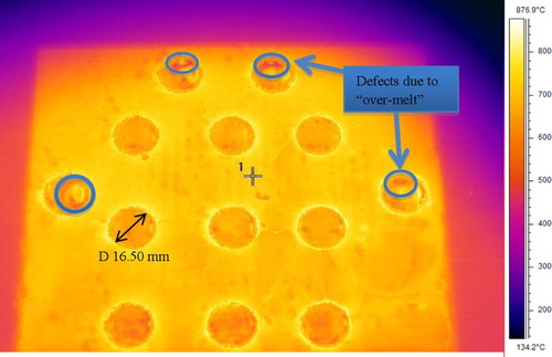
46 Near IR imaging of Ti–6Al–4V tensile specimens used to identify defects258
Post-build, non-destructive techniques can be used to detect internal defects.223 The Archimedes principle of immersion in liquid can be used to detect the presence of large amounts of porosity, but it may overestimate low amounts of porosity due to entrapment of air bubbles. XRCT and neutron tomography do not have bubble entrapment issues but will still have associated counting statistical error. XRCT and the Archimedes principle have been shown to be in general agreement, but the Archimedes method is noted to be faster and more economical for bulk measurements.224 The benefit of XRCT and neutron tomography is that porosity mapping can be done to determine the locations of defects. Ultrasonic transducers are capable of detecting smaller amounts of porosity (∼0·5%) and should also be capable of porosity mapping.
Some monitoring techniques have been implemented commercially, while others not. Pyrometry has been implemented with some DED processes to affect process control. Layer imaging using standard cameras has been implemented commercially on some EBM systems. Effective IR imaging and process feedback has yet to be implemented in any commercial system, but is a good option for users demanding better quality assurance.
Comparison
Now that the general processing science of metal AM has been explored, this background can be used to compare the technical aspects of existing technologies. A tabulated comparison of SLM, EBM, powder-fed DED, wire-fed DED, Binder Jetting and Sheet Lamination is given in Table 6. Discussion will focus on just a few of the more interesting differences. For example, porosity can be kept to low levels in PBF and DED but is inherently present in Binder Jetting. Binder Jetting must address the porous nature of the material by either infiltration of consolidation. EBM and Binder Jetting are notable for low levels of residual stress induced during processing. This can be attributed to a high operating temperature for the EBM process (effectively in situ stress relief) and no differential applied temperature during Binder Jetting processing (heating occurs to whole part during thermal post-processing). The high operating temperature of EBM does reduce residual stress levels, but can lead to concerns with in situ aging of the microstructure. While Binder Jetting does have many advantages, is also has its own set of concerns associated with fragile green bodies and post-processing. PBF and Binder Jetting are the more capable techniques for producing complex geometries such as overhangs and meshes. Surface finish may be best on SLM and Sheet Lamination systems but, as mentioned before, all metal AM parts should be considered net shapes; machining must be done after thermal post-processing for most uses. Sheet Lamination achieves a machined finish because machining is done as part of the process, after each layer. Process clean-up is really only a concern in PBF and Binder Jetting processes. Powder must be sieved and handled appropriately. Additionally, EBM partially sintered powder must be blasted away from the surface of finished parts (which adds an additional step). The use of DED for deposition on top of existing structures enables its unique use for part repair. Multi-material parts can only be produced using Sheet Lamination (layers of different materials), Binder Jetting (infiltration) or DED (multiple wire or powder feeds).
The metallurgy and processing science of metal additive manufacturing
Published online:
07 March 2016Table 6. Comparison of defects and features across platforms
Process speed, or deposition rate, is a major limitation of current metal AM techniques. Current deposition rates are presented in Table 7. The fastest deposition rate (based on the minimum of the listed ranges of deposition rates) is using Binder Jetting, which does not melt or sinter the metal. The increase in deposition speed comes at the cost of additional post-processing steps (curing, sintering, etc.). The wire-fed DED process known as EBFFF and produced by the company Sciaky is also arguably the fastest deposition rate (based on upper deposition ranges estimates). The difference between the EBFFF and Sciaky processes as listed in Table 7 can be attributed to the differences in maximum power of each system; the data and deposition rates for the ‘Sciaky’ process are from 2015, whereas earlier data on EBFFF from 2002 can be assumed to present older models. These separate data points show the significant progress that has been made in terms of deposition rate for wire-fed DED in the last 10+ years. Powder-fed DED can be fast – if a larger power laser is used. The same principle is true of all processes that use a heat source; faster deposition rates can be achieved with higher power input. Higher power allows for faster scan speeds to achieve the same energy density needed for full melting. EBM is reportedly faster than SLM, making it the faster PBF technique. SLM deposition rate can be increased at the expense of surface finish. Depending on part requirements, SLM operators should consider this to decrease build time. Unless higher power heat sources are used, wire-fed DED is reportedly at least three-times faster than powder-fed DED. More efficient deposition of material can explain this, as some powder is lost during the spray process (and cooling incurred by the gas flow). For comparison to consumer polymer hardware, the RepRap deposition rate was included. All metal AM volumetric deposition rates (though mass deposition rates of metals are much higher) are on the same order of magnitude as these polymer printers, except for the high-power LENS and ExOne systems. In addition to deposition rate, the maximum power input is another typical figure of merit. This value is helpful for describing how much power can be applied to a given area. Though there is no clear relationship between max power input and deposition rate, max power input is useful for determining process efficiency and deducing the impact on microstructure (see previous section).
The metallurgy and processing science of metal additive manufacturing
Published online:
07 March 2016Table 7. Reported deposition rates for various technologies
Applications and economics
Metal AM has found a range of applications within the aerospace, biomedical, automotive, robotics and many other industries. Applications in part repair are mostly limited to the aerospace industry, whereas all industries mentioned are beginning to use metal AM for end-use part production. However, limited build volumes, slow deposition rates, high feedstock costs and high machine costs limit the current use of the technology. With these constraints, AM technologies are mostly limited to uses in low-volume production, material use reduction and cases of necessity (cases where the only production method available for a particular geometry is AM). The complexity of part geometry is critical in determining the point at which AM becomes an economically viable production pathway. Process improvements and quality controls may help to lower the costs associated with AM production in the future.
Market analysts predict the overall market for AM (metal and polymer) parts will grow by 18% a year until 2025, reaching a market size of $8·4 billion.225,226 The largest growth areas are projected to be aerospace, biomedical and automotive. Due to the nature of the parts needed by these industries, a significant portion of that growth can be expected to come from metal AM processes. In fact, the aerospace and medical industries have been early adopters and users of metal AM parts for end-use. The material of choice for these industries has been Ti–6Al–4V, for use as a light-weight structural material and as a bio-compatible material. Case studies for aerospace parts have demonstrated AM brackets152 and landing gears.227 The development of Inconel 718 and other superalloys has been sponsored for use in aerospace components, but could be used in any industry that has the need for high temperatures or superalloy components. GE Aviation, a large company in the aerospace field, has committed to production of fuel injectors for the LEAP engine228 and γ-TiAl turbine blades for the GEnX engine.229 The aerospace industry has also found use for DED systems in turbine blade repair,155 including repair of single crystal material.173 The use for part repair is limited to cases of high-cost parts, where the cost of repair is lower than the cost of replacement. For this reason, most AM research focuses on the production of end-use parts, fabricated without an existing component.
Case studies for biomedical parts have demonstrated AM bone replacements for jaws,230 hips and other parts. Custom dental implants are now commonly made231 of CoCr alloys using SLM (displacing CNC machining), but may require annealing to achieve ideal microstructure.232 At a market size of $11·2 billion in 2011, the dental prosthetics market is growing and is a significant application area for metal AM.233 The application of mesh structures is attractive for biomedical parts48 and also has applications for other uses, such as lithium ion batteries.234 The use of light-weight Ti–6Al–4V has been demonstrated for use in robotics (Fig. 47), as the use of AM can enable additional degrees of freedom and allow for internal routing of hydraulic and electrical lines.235
The metallurgy and processing science of metal additive manufacturing
Published online:
07 March 201647 Failed build due to selective powder fetching in EBM. Hardware/software advances are needed to eliminate such problems
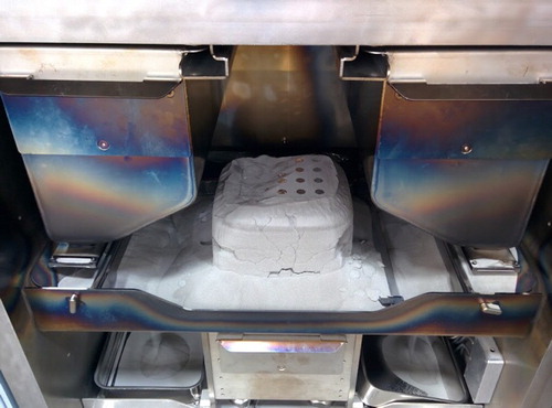
47 Failed build due to selective powder fetching in EBM. Hardware/software advances are needed to eliminate such problems
To analyse the economics of AM, a comparison to traditional methods and subtractive manufacturing is necessary. Cost models for SLM have been developed and can calculate costs for multiple parts in a batch.236 When comparing SLM to die casting, AM is more economical only for low volumes (less than 31 parts for the geometry studied).237 This cost comparison to die cast parts assumed a change in material from AlSi12Cu1(Fe) to AlSi10Mg, which may not be possible for all use cases. Alternatively, PBF and DED processes have been explored for use in producing tooling inserts for die casting of aluminium and shown to match performance (and in some cases improve performance under cyclic heat testing) of conventionally machined inserts.238 Compared to subtractive manufacturing, AM also only makes sense for small volumes or where the ‘buy-to-fly’ ratio (amount of material consumed compared to the amount that is actually used in the final product) is high.239 Figure 48 shows a comparison of AM to subtractive manufacturing (where parts are machined from a block of starting material). According to this model, the cost of labor/design and the failure rate are extremely important to the viability of AM. Increasing deposition rate can also dramatically increase the range of cases where AM is viable.
The metallurgy and processing science of metal additive manufacturing
Published online:
07 March 201648 Joint of a robotic arm that embeds hydraulic lines, eliminating external lines for hydraulic fluid and wiring (used with permission)235
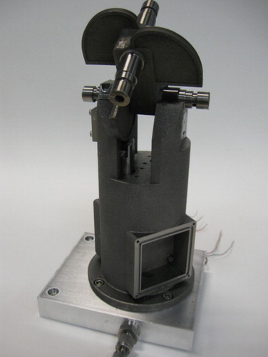
48 Joint of a robotic arm that embeds hydraulic lines, eliminating external lines for hydraulic fluid and wiring (used with permission)235
These analyses mean that AM is currently economically limited for end-use parts, for small quantities of parts or parts that require large billets to be used during machining. For the remaining uses, the viability of AM comes down to economy vs. necessity (which is not completely unrelated). By enabling new geometries that reduce the number of components in a part (like the GE LEAP nozzle) or mesh structures that promote body acceptance of implants (for medical implants), metal AM has the potential to make economic sense by displacing parts with inferior performance. This nuance (that AM then becomes a necessity to make the new, more efficient part design) is lost in some analyses of manufacturing economics (only looking at volumes, raw material costs and manufacturing efficiency). This means that the key for the growth of metal AM is to find more design improvements that are enabled by AM and/or finding ways to reduce the driving costs of using metal AM for production.
Of paramount importance is the reduction of failure rates in AM processes, which are held as proprietary information and not typically published or quoted. It has been shown that a failure rate of just 10% can make AM processes un-economical.239 Better quality control and improved hardware/software designs will surely help. For those familiar with equipment from the last decade, there is a ‘Rule of 4’ that has been used to describe the success rate of AM; it can take up to three iterations to produce a successful outcome, but after that the desired parts can be produced reliably. While this is viable for a standardised batch of parts, the trial and error associated with delivering new geometries must be eliminated to make AM viable for one-off parts. Hardware reliability must improve across all systems. For example, the result of selective powder fetching (only fetching powder from one hopper) in EBM is shown in Fig. 49. For this build, powder distribution sensors failed to recognise powder as present in both hoppers. The machine then fetched powder from only one hopper, leaving the other completely full. The build then failed due to running out of powder (the left side of the build can be seen as depressed). There are many other machine reliability problems across platforms, and this example should be taken to highlight the kind of problems that must be overcome. Developments in technology continue to improve success rates, as does the development of a workforce skilled in AM. A skilled operator can boost success rates tremendously for most metal AM processes.
The metallurgy and processing science of metal additive manufacturing
Published online:
07 March 201649 Comparative analysis of additive and subtractive manufacturing239
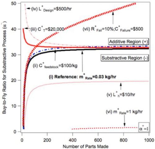
49 Comparative analysis of additive and subtractive manufacturing239
The application area is not just limited by cost, but also by capabilities of AM machines. Small build volumes mean that parts of or greater than the meter-scale are not possible with the current technology. Slow deposition rates are a limiting feature in some processes from the standpoint that there are hardware limitations on extremely long build times. For example, EBM processing is limited in the maximum time possible by filament lifetime (typically replaced every 100 hours of burn time). The exception to small build volumes and slow deposition rates is wire-fed DED processing, which can build up to 7112 mm × 1219 mm × 1219 mm parts (in a Sciaky EBAM 300).240
Optics in laser based systems must not get dirty or heat up during long build operations. From this viewpoint, extremely long build times (>100 hours) are not just uneconomical but also not possible due to hardware constraints. Very small parts cannot be made due to limitations on machine resolution based on material feedstock and heat source size. Overhangs and complex geometries continue to be a limitation; though PBF and Binder Jetting have mostly enabled parts with this feature (supports are typically necessary in PBF).
Input costs (hardware, feedstock, maintenance, etc.) are high for metal AM and significantly limit the current metal AM market to researchers and large industrial users. Machine costs are not widely reported and vary based on model type. Some available hardware cost information has reported the following values: ExOne models range from $145 000–950 000,241,242 the EOS M270/M280 is $800 000,243 Arcam models range from $0·6 to 1·3 Million244 and the Renishaw AM250 is $750 000.245 Based on these reported prices, hardware costs appear pretty similar across platforms. Costs for DED and Sheet Lamination systems remain unreported, but are expected to be similar to SLM, EBM and Binder Jetting. At a price of $0·5–1 Million, metal AM hardware is a significant capital investment for most companies. Hardware is not the only major cost in operating a system; feedstock costs can be a significant investment as well. Powder feedstock costs are typically higher than wire costs, and are a significant investment for powder-based processes. The powder used in some SLM metal machines has been reported to vary from $120 kg−1 for stainless steel to $735 kg−1 for Ti–6Al–4V ELI.246 SLM processes require a smaller particle size distribution, which tends to cost a premium due to the yields of current powder production techniques. Cost is highly dependent upon atomisation technique, which can determine powder quality. Typical techniques used for AM powders are GA ($165–330 kg−1), PA and PREP ($407–1210 kg−1).247 Binder Jetting particle size distributions are not well known and costs are not reported. Based on similar particle size requirements to EBM, powder-fed DED powder is expected to have similar costs.
Conclusion
This review details processing defects, thermal histories, post-processing, microstructure and mechanical properties associated with DED and PBF techniques. The various metal AM techniques were described, with a focus on comparison of processing strengths and weaknesses. Previous work identified future directions for metal AM within specific areas: limited deposition rate, surface finish, residual stress and microstructural variations.248 It is useful to consider the progress that has been made in these areas since the publication of the report in 2007 and identify new directions that the technology may take.
Higher power lasers have increased the deposition rate of some DED hardware. Currently, surface finish and deposition rate are inversely related, which is an undesirable trade-off. Many experiments try to improve surface finish, despite the fact that most end-use parts will be post-processed (thermally and mechanically) and surface finish will be determined by the polishing or machining techniques used. If this is the intended use, surface finish almost does not matter.
Residual stress continues to be a defining problem for DED and SLM, but new technologies like EBM (and potentially Binder Jetting) have succeeded in producing parts with low amounts of residual stress. Residual stress can impact post-processing and mechanical properties. Acting as a driving force for recrystallisation, residual stress in DED and SLM parts may limit the ability to engineer grain structures using those approaches. Conversely, residual stress may be able to be used to help promote recrystallisation and the formation of equiaxed microstructures.
The understanding of the microstructure, mechanical properties and processability of new alloys has been the main advance in metal AM in the past five years. While microstructural heterogeneities are still observed, characterisation work has shown certain features (columnar grains, high orientation, amount of porosity, etc.) to persist across technologies and materials for as-fabricated material. It should be noted that this generalisation must be qualified; post-processing has been reviewed herein and shown to impact the columnar structure in various materials (Fe,100 IN718,144 Ti–6Al–4V140) for certain processes (DED and PBF). Therefore, microstructural discussions and generalisations between AM processes must consider the post-processing (including stress relief) performed on the material. Improved process control and processing experience have allowed for the reduction of process-induced porosity to levels of frequently >99% dense parts.
Two current mindsets for metal AM material exist: (1) as-fabricated properties matter because there are customers who intend to use them without post-processing and (2) as-fabricated properties are not important because material will be post-processed to eliminate pores and cracks, change the grain structure and change phase fractions. Both these schools of thought are relevant, but it is important to note that as-fabricated microstructure is still important to characterise even if post-processing is to be used; post-processing needs to consider the as-fabricated properties in order to achieve the desired final material. For this reason, work to characterise as-fabricated material will continue to be important to both schools of thought. As processes improve, the process metallurgy is likely to change the condition of as-fabricated material (even for those materials previously characterised).
Niche product applications (hip replacements, GE LEAP nozzles, GE turbine blades) have found recent success for the use of PBF parts. Previous success was mostly in the DED repair of traditional parts for the aerospace industry. (REF blades) Applications to the robotics industry are promising, as metal AM has been shown to enable performance characteristics, like increasing the degrees of freedom of rotating parts. All of these developments suggest that metal AM may really be about ‘giant engineering firms turning out sophisticated parts’.249
Future directions
The future of the technology is bright. Improvements on the high end will enable the production of higher quality AM parts, while the expiration of patents and falling costs of heat sources will help to lower the cost of the technology. New materials will be processed, offering a wider range of available alloys. Recent work on the control of grain structure and phase formation suggests that improvements in processing controls will enable metal AM to achieve microstructural engineering on a scale not previously possible.
Having explored the current state of metal AM, it is useful to look back on where limitations exist. The authors have identified the following areas as being of general importance for the continued improvement of metal AM:
Faster deposition rates
Quality control
Machine reliability
Cost reduction
New capabilities/materials
Faster deposition rates are directly related to costs and feasibility. Faster rates mean that more parts can be produced per machine per unit time. Deposition rates may be increased some by using larger layer thicknesses. To achieve even faster deposition rates, limitations on the amount of power input available for the process must increase. This is possible by increasing the power or number of heat sources available. Faster deposition must not incur too much residual stress, or significant warping issues may occur. Some increase in the amount of defects (like porosity) may be tolerated, if post-processing can be done.
Quality control is a significant concern and problem for industries using metal AM processes. Metal AM processes are new (compared to traditional processes) and are just beginning to enter the time frame for qualification for many aerospace companies, though biomedical qualification may offer a shorter timeline. Quality control must understand the details of the AM process to be qualified. For this reason, advances in process technology may not get incorporated as fast (as industry is likely to qualify certain machines and older software versions). A NIST roadmap for metal AM focuses entirely on quality control concerns: standards and protocols, measurement and monitoring techniques for data, fully characterised material properties, modelling systems that couple design and manufacturing, and closed loop control systems for AM.250 Developing quality control, and keeping it up-to-date, is likely to remain a focus of metal AM (as it has since 2009 when leaders in the field of AM published a roadmap251 that included similar concerns to the 2013 NIST roadmap). These are all extremely important efforts, but quality control is only one piece of the big picture.
Machine reliability of all metal AM systems must improve, and the operator burden should be reduced. High failure rates are common in many systems, though these rates are hardware, operator and design dependent. Though improvement of machine reliability must come from hardware manufacturers, researchers and operators should come together to present best practices to reduce the effect of operator error on failure rates. Improved software simulation could also play an important role in determining optimal build orientations for successful builds. As more technicians learn how to use existing hardware, operator errors will also be reduced.
The impact of cost cannot be understated. It can be argued that faster deposition rates, quality control and machine reliability are really just sub-sets of cost. Cost is considered separately here, as reduction in hardware and feedstock costs can open up the metal AM market to completely new customers. While consumer metal printers are not likely to happen anytime soon (though open source efforts are making progress), a significant drop in hardware cost could open up the machine shop market; machine shops are a significant player in local manufacturing and have more resources to support hardware than typical consumers. Continued costs reductions should be expected to open up metal AM to more users, while increasing the number of uses considered economical.
New hardware and new materials development have the most direct impact to the research community. Development of new ways of processing metal into parts could potentially dramatically increase deposition rates and lower costs of metal AM (in the way in which large-scale polymer systems have changed what is possible with polymer printing). New materials development is research intensive but necessary to increase the number of uses for metal AM. New alloys will have uses for new industries and new parts. AM-specific alloys may be able to increase performance beyond what is capable with traditional wrought or cast alloys. The ability to manipulate grain and phase structures offers the potential for microstructural engineering and will likely see continued efforts. Fundamental processing science is important to all of these development efforts.
Research sponsored by the U.S. Department of Energy, Office of Energy Efficiency and Renewable Energy, Advanced Manufacturing Office, under contract DE-AC05–00OR22725 with UT-Battelle, LLC. This research was also supported by fellowship funding received from the U.S. Department of Energy, Office of Nuclear Energy, Nuclear Energy University Programmes. The United States Government retains and the publisher, by accepting the article for publication, acknowledges that the United States Government retains a non-exclusive, paid-up, irrevocable, world-wide licence to publish or reproduce the published form of this manuscript, or allow others to do so, for United States Government purposes.
ORCID
W. J. Sames http://orcid.org/0000-0001-8701-9166
S. Pannala http://orcid.org/0000-0001-5040-1222
S. S. Babu http://orcid.org/0000-0002-3531-2579
| Process | Patent number | Patent priority date | Inventor | Original associated corporation |
|---|---|---|---|---|
| SLS 7 | WO1988002677 A2 | 1986 | Carl Deckard | University of Texas |
| ‘3D Printing’ 8 (binder deposition) | US5204055 A | 1989 | Cima et al. | MIT |
| EBM259 | US7537722 B2 | 2000 | Lars-Erik Andersson & Morgan Larsson | Arcam AB |
| LENS260 | US6046426 A | 1996 | Jeantette et al. | Sandia Corporation |
| UAM11 | US6519500 | 1999 | Dawn White | Solidica |
| Process | Typical layer thickness/µm | Minimum feature size or beam diameter/µm |
|---|---|---|
| PBF – SLM142 | 10–50 | 75–100 |
| PBF – EBM | 50 | 100–200 |
| DED – powder fed81 | 250 | 380 |
| DED – wire fed67 | 3000 | 16 000 |
| Treatment | Ti–6Al–4V | Inconel 718 |
|---|---|---|
| Stress relief | 2 hours, 700–730°C197 | 0·5 hours at 982°C142 1065 ± 15°C for 90 min (−5±15 min)193 |
| Hot isostatic pressing (HIP) | 2 hours, 900°C, 900 MPa197 180 ± 60 min, 895–955°C, >100 MPa192 | 4 hours at 1120°C, 200 MPa |
| Solution treat (ST) | Not typical | 1 hour at 980°C261 |
| Aging | Not typical | 8 hours at 720°C Cool to 620°C Hold at 620°C for 18 hours total261 |
| Process | Commercial materials | Researched materials |
|---|---|---|
| DED | Stainless steel, Ni-based alloys, tool steel, Ti alloys | FeTiNi,161 TiZrNbMoV,160 ceramics,162 CoCrMo,262 WC-Co163 |
| EBM | Ti–6Al–4V, Ti, CoCr263 | Inconel 718, Inconel 625, Al 2024,73 high purity copper,183 GRCop-84,164 Niobium,264 bulk metallic glass,158 stainless steel 316L,87 TiAl,265 CMSX-4266 |
| LM | Ti–6Al–4V, stainless steel, various steels, Ti, CoCr, Al–Si–10Mg, bronze, precious metals, Inconel 718, Inconel 625, Hastelloy X | Tantalum,177 W-Ni,267 AlSi10Mg175 |
| Sheet lamination257 | Al/Cu, Al/Fe, Al/Ti | Ta/Fe, Ag/Au, Ni/stainless |
| Binder deposition | 316 Stainless steel infiltrated with bronze, 420 stainless steel infiltrated with bronze (annealed & non-annealed), bronze, iron infiltrated with bronze, bonded tungsten,26 Inconel 625268 | FeMn,269 pure alloys (no infiltration), ceramics270 |
| Material | 0·2% YS/MPa | UTS/MPa | Elongation/% | Reference |
|---|---|---|---|---|
| Ti–6Al–4V | ||||
| DED as-deposited (X–Y) | 976±24 | 1099±2 | 4·9±0·1 | 169 |
| DED stress relieved (X–Y) | 1065–1066 | 1109 | 4·9–5·5 | 197 |
| DED stress relieved (Z) | 832 | 832 | 0·8 | 197 |
| DED HIP (X–Y) | 946–952 | 1005–1007 | 13·0–13·1 | 197 |
| DED HIP (Z) | 899 | 1002 | 11·8 | 197 |
| LM as-fabricated (X–Y) | 910±9·9 | 1035±29·0 | 3·3±0·76 | 168 |
| LM + HT (X–Y) | 1195±19·89 | 1269±9·57 | 5±0·52 | 189 |
| LM + HT (Z) | 1143±38·34 | 1219±20·15 | 4·89±0·65 | 189 |
| EBM as-fabricated (X–Y) | 967–983 | 1017–1030 | 12·2 | 191 |
| EBM as-fabricated (Z) | 961–984 | 1009–1033 | 7·0–9·0 | 191 |
| EBM as-fabricated (Z) | 883·7–938·5 | 993·9–1031·9 | 11·6–13·6 | 167 |
| EBM HIP (Z) | 841·4–875·2 | 938·8–977·6 | 13·4–14·0 | 167 |
| Wrought bar (annealed) | 827–1000 | 931–1069 | 15–20 | 271 |
| Cast+anneal | 889 | 1014 | 10 | 271 |
| Cast+anneal (peak aged) | 1170 | 1310 | – | 189,272 |
| Inconel 718 | ||||
| DED as-deposited (NR) | 590 | 845 | 11 | 53 |
| DED STA (X–Y) | 635–1107 | 958–1415 | 2·4–18·4 | 170 |
| LM as-fabricated (NR) | 889–907 | 1137–1148 | 19·2–25·9 | 171 |
| LM STA (NR) | 1102–1161 | 1280–1358 | 10·0–22·0 | 171 |
| LM as-fabricated + stress relief (X–Y) | 830 | 1120 | 25 | 142 |
| LM HIP+anneal (X–Y) | 890 | 1200 | 28 | 142 |
| LM HIP+anneal (Z) | 850 | 1140 | 28 | 142 |
| EBM as-fabricated (X–Y) | 822 ± 25 | 1060 ± 26 | 22 | 150 |
| EBM as-fabricated (Z) | 669–744 | 929–1207 | 21–22 | 148,150 |
| EBM HIP+STA (X–Y) | 1154 ± 46 | 1238 ± 22 | 7 | 150 |
| EBM HIP+STA (Z) | 1187 ± 27 | 1232 ± 16 | 1·1 | 150 |
| Wrought – bar | 1190 | 1430 | 21 | 272 |
| Wrought – sheet | 1050 | 1280 | 22 | 272 |
| Defect or feature | LM | EBM | DED – powder fed | DED – wire fed | Binder jetting | Sheet lamination |
|---|---|---|---|---|---|---|
| Feedstock | Powder | Powder | Powder | Wire | Powder | Sheets |
| Heat source | Laser | E-beam | Laser | Laser/E-beam | N/A; kiln | N/A; ultrasound |
| Atmosphere | Inert | Vacuum | Inert | Inert/vacuum | Open air | Open air |
| Part repair | No | No | Yes | Yes | No | No |
| New parts | Yes | Yes | Yes | Yes | Yes | Yes |
| Multi-material | No | No | Possible | Possible | Infiltration | Yes |
| Porosity | Low | Low | Low | Low | High | At sheet interfaces |
| Residual stress | Yes | Low | Yes | Yes | Unknown | Unknown |
| Substrate adherence | Yes | Material dependent | Yes | Yes | N/A | Yes |
| Cracking | Yes | Not typical | Yes | Yes | Fragile green bodies | No |
| Delamination | Yes | Yes | Yes | Yes | No | Yes |
| Rapid solidification | Yes | Yes | Yes | Yes | No | No |
| In situ aging | No | Yes | No | No | No | No |
| Overhangs | Yes | Yes | Limited | Limited | Yes | Limited |
| Mesh structures | Yes | Yes | No | No | Limited | No |
| Surface finish | Medium-rough | Rough | Medium-poor | Poor but smooth | Medium-rough | Machined |
| Build clean-up from process | Loose powder | Sintered powder | Some loose powder | N/A | Loose powder | Metal shavings |
| Process | Machine | Deposition Rate/cc h−1 | Maximum power/W | Min. heat source diameter/mm | Max. power input/kW mm−1 |
|---|---|---|---|---|---|
| Binder Jetting | M-Flex273 | 1200–1800 | N/A | N/A | N/A |
| DED – wire fed | Sciaky240 | 700–2000 | 42 000 | 0·38a | 370 |
| DED – powder fed | LENS (2500–3000W)20 | 230 | 3000 | 1 | 3·8 |
| EBM | A2243 | 60 | 3500 | 0·2 | 110 |
| DED – wire fed | EBFFF21 | 47 | 408 | 0·38 | 3·6 |
| Material extrusion | RepRap, Polymer274 | 33 | N/A | N/A | N/A |
| SLM | Renishaw AM 250275 | 5–20 | 400 | 0·135 | 28 |
| DED – powder fed | LENS (400–500W)20 | 16 | 500 | 1 | 0·64 |
aIt is assumed that the minimum heat source diameter for the new Sciaky model is the same as previously reported for EBFFF for the calculations in this table.
- C. R. Deckard: ‘Part generation by layer-wise selective laser sintering’, MS thesis, Univeristy of Texas, Austin, TX, 1986.
- A. Lou and C. Grosvenor: ‘Selective laser sintering, birth of an industry’, 2012. Available at http://www.me.utexas.edu/news/2012/0712_sls_history.php (November 4, 2014)
- C. R. Deckard: ‘Selective laser sintering’, PhD thesis, Univeristy of Texas, Austin, TX, 1988.
- D. L. Bourell, H. L. Marcus, J. W. Barlow and J. J. Beaman: ‘Selective laser sintering of metals and ceramics’, Int. J. Powder Metall., 1992, 28, 369–381.,
- H. L. Marcus, D. L. Bourell, J. J. Beaman, A. Manthiram, J. W. Barlow and R. H. Crawford: ‘Challenges in laser processed solid freeform fabrication’, Processing and Fabrication of Advanced Materials III, proceedings of the 1993 TMS materials week conference, Pittsburgh, PA, 17–21 October 1993, 127–133.
- J. A. Manriquez-Frayre and D. L. Bourell: ‘Selective laser sintering of binary metallic powder’, in ‘Solid freeform fabrication symposium’, Austin, TX, 1990, 99–106.
- C. R. Deckard: ‘Method and apparatus for producing parts by selective sintering’, PCT Patent WO1988002677 A2, 1986.
- M. J. Cima, J. S. Haggerty, E. M. Sachs and P. A. Williams: ‘Three-dimensional printing techniques’, US Patent US5204055 A, 1989.
- EOS-GmbH: ‘History’. Available at http://www.eos.info/about_eos/history (April 16, 2014)
- Sandia-National-Laboratories: ‘Creating a complex metal part in a day is goal of commercial consortium’. Available at http://www.sandia.gov/media/lens.htm
- D. White: ‘Ultrasonic object consolidation’, US Patent US6519500 B1, 1999.
- R. Larson: ‘Method and device for producing three-dimensional bodies’, US Patent US5786562 A, 1993.
- Arcam-AB: ‘Arcam History’. Available at http://www.arcam.com/company/about-arcam/history/ (April 16, 2014)
- ASTM-International: ‘Standard terminology for additive manufacturing technologies’, vol. F2792-12a, ed. West Conshohocken, PA, ASTM International, 2012.
- J. P. Kruth, X. Wang, T. Laoui and L. Froyen: ‘Lasers and materials in selective laser sintering’, Assembly Autom., 2003, 23, 357–371. doi: 10.1108/01445150310698652,
- W. J. Sames, F. Medina, W. H. Peter, S. S. Babu and R. R. Dehoff: ‘Effect of process control and powder quality on Inconel 718 produced using electron beam melting’, in ‘Superalloy 718 and derivatives’, Pittsburgh, PA, 2014.
- P. Vallabhajosyula and D. L. Bourell: ‘Indirect selective laser sintered fully ferrous components – infiltration modeling, manufacturing and evaluation of mechanical properties’, in ‘Solid freeform fabrication symposium’, Austin, TX, 2009.
- S. Kumar and J. P. Kruth: ‘Effect of bronze infiltration into laser sintered metallic parts’, Mater. Des., 2007, 28, 400–407. doi: 10.1016/j.matdes.2005.09.016,
- M. L. Griffith, D. L. Keicher, J. T. Romero, J. E. Smugeresky, C. L. Atwood, L. D. Harwell and D. L. Greene: ‘Laser Engineered Net Shaping (LENSTM) for the fabrication of metallic components’, in Proc. of the ‘1996 ASME international mechanical engineering congress and exposition’, November 17, 1996–November 22, 1996, Atlanta, GA, USA, 1996, 175–176.
- R. P. Mudge and N. R. Wald: ‘Laser engineered net shaping advances additive manufacturing and repair’, Weld. J., 2007, 86, 44–48.,
- J. E. Matz and T. W. Eagar: ‘Carbide formation in alloy 718 during electron-beam solid freeform fabrication’, Metall. Mater. Trans. A, 2002, 33, 2559–2567. doi: 10.1007/s11661-002-0376-y,
- B. Baufeld, E. Brandl and O. van der Biest: ‘Wire based additive layer manufacturing: Comparison of microstructure and mechanical properties of Ti–6Al–4 V components fabricated by laser-beam deposition and shaped metal deposition’, J. Mater. Process. Technol., 2011, 211, 1146–1158. doi: 10.1016/j.jmatprotec.2011.01.018,
- J. Xiong and G. Zhang: ‘Adaptive control of deposited height in GMAW-based layer additive manufacturing’, J. Mater. Process. Technol., 2014, 214, 962–968. doi: 10.1016/j.jmatprotec.2013.11.014,
- S. W. Williams, F. Martina, A. C. Addison, J. Ding, G. Pardal and P. Colegrove: ‘Wire + Arc additive manufacturing’, Mater. Sci. Technol., 2015. doi:10.1179/1743284715Y.0000000073,
- J. Gu, B. Cong, J. Ding, S. Williams and Y. Zhai: ‘Wire+arc additive manufacturing of aluminium’, in ‘Solid freeform fabrication symposium’, Austin, TX, 2014.
- ExOne : ‘Metal’. Available at http://www.exone.com/en/materialization/what-is-digital-part-materialization/metal (April 15, 2014)
- G. N. Levy, R. Schindel and J. P. Kruth: ‘Rapid manufacturing and rapid tooling with layer manufacturing (LM) technologies, state of the art and future perspectives’, CIRP Ann. Manuf. Technol., 2003, 52, 589–609. doi: 10.1016/S0007-8506(07)60206-6,
- T. Obikawa, M. Yoshino and J. Shinozuka: ‘Sheet steel lamination for rapid manufacturing’, J. Mater. Process. Technol.J. Mater. Process. Technol., 1999, 89–90, 171–176. doi: 10.1016/S0924-0136(99)00027-8,
- S. Yi, F. Liu, J. Zhang and S. Xiong: ‘Study of the key technologies of LOM for functional metal parts’, J. Mater. Process. Technol., 2004, 150, 175–181. doi: 10.1016/j.jmatprotec.2004.01.035,
- H. Thomas, T. Anja, N. Steffen and B. Eckhard: ‘Recent developments in metal laminated tooling by multiple laser processing’, Rapid Prototyping J., 2003, 9, 24–29. doi: 10.1108/13552540310455629,
- B. Xu, X.-Y. Wu, J.-G. Lei, F. Luo, F. Gong, C.-L. Du, X.-Q. Sun and S.-C. Ruan: ‘Research on micro-electric resistance slip welding of copper electrode during the fabrication of 3D metal micro-mold’, J. Mater. Process. Technol., 2013, 213, 2174–2183. doi: 10.1016/j.jmatprotec.2013.06.009
- B. Mueller and D. Kochan: ‘Laminated object manufacturing for rapid tooling and patternmaking in foundry industry’, Comput. Ind., 1999, 39, 47–53. doi: 10.1016/S0166-3615(98)00127-4,
- T. Himmer, T. Nakagawa and M. Anzai: ‘Lamination of metal sheets’, Comput. Ind., 1999, 39, 27–33. doi: 10.1016/S0166-3615(98)00122-5,
- D. R. White: ‘Ultasonic consolidation of aluminum tooling’, Adv. Mater. Process., 2003, 161, 64–65.,
- Fabrisonic: ‘Ultrasonic additive manufacturing’, 2011. Available at https://www.youtube.com/watch?v=5s0J-7W4i6s (May, 2015)
- R. J. Friel and R. A. Harris: ‘Ultrasonic additive manufacturing – a hybrid production process for novel functional products’, Proc. CIRP, 2013, 6, 35–40. doi: 10.1016/j.procir.2013.03.004,
- S. Masurtschak, R. J. Friel, A. Gillner, J. Ryll and R. A. Harris: ‘Fiber laser induced surface modification/manipulation of an ultrasonically consolidated metal matrix’, J. Mater. Process. Technol., 2013, 213, 1792–1800. doi: 10.1016/j.jmatprotec.2013.04.008,
- G. D. J. Ram, C. Robinson, Y. Yang and B. E. Stucker: ‘Use of ultrasonic consolidation for fabrication of multi-material structures’, Rapid Prototyping J., 2007, 13, 226–235. doi: 10.1108/13552540710776179,
- M. R. Sriraman, S. S. Babu and M. Short: ‘Bonding characteristics during very high power ultrasonic additive manufacturing of copper’, Scr. Mater., 2010, 62, 560–563. doi: 10.1016/j.scriptamat.2009.12.040,
- R. Hahnlen and M. J. Dapino: ‘NiTi–Al interface strength in ultrasonic additive manufacturing composites’, Composites B: Eng., 2014, 59, 101–108. doi: 10.1016/j.compositesb.2013.10.024,
- D. E. Schick, R. M. Hahnlen, R. Dehoff, P. Collins, S. S. Babu, M. J. Dapino and J. C. Lippold: ‘Microstructural characterization of bonding interfaces in aluminum 3003 blocks fabricated by ultrasonic additive manufacturing’, Weld. J., 2010, 89, 105s–115s.
- R. R. Dehoff and S. S. Babu: ‘Characterization of interfacial microstructures in 3003 aluminum alloy blocks fabricated by ultrasonic additive manufacturing’, Acta Mater., 2010, 58, 4305–4315. doi: 10.1016/j.actamat.2010.03.006,
- H. Fujii, M. R. Sriraman and S. S. Babu: ‘Quantitative evaluation of bulk and interface microstructures in Al-3003 alloy builds made by very high power ultrasonic additive manufacturing’, Metall. Mater. Trans. A, 2011, 42, 4045–4055. doi: 10.1007/s11661-011-0805-x,
- K. Sojiphan, S. S. Babu, X. Yu and S. C. Vogel: ‘Quantitative evaluation of crystallographic texture in aluminum alloy builds fabricated by very high power ultrasonic additive manufacturing’, Presented at the ‘Solid Freeform Fabrication Symposium’, Austin, TX, 2012.
- M. R. Sriraman, M. Gonser, H. T. Fujii, S. S. Babu and M. Bloss: ‘Thermal transients during processing of materials by very high power ultrasonic additive manufacturing’, J. Mater. Process. Technol., 2011, 211, 1650–1657. doi: 10.1016/j.jmatprotec.2011.05.003,
- A. Herr, J. Pritchard and M. Dapino: ‘Interfacial shear strength estimates of NiTi-Al matrix composites fabricated via ultrasonic additive manufacturing’, Proceedings of SPIE – The international society for optical engineering, industrial and commercial applications of smart structures technologies, 2014, vol. 9059, article number: 905906.
- I. Gibson, D. W. Rosen and B. Stucker: ‘Additive manufacturing technologies’, 2010,
New York, NY , Springer., - L. E. Murr, S. M. Gaytan, D. A. Ramirez, E. Martinez, J. Hernandez, K. N. Amato, P. W. Shindo, F. R. Medina and R. B. Wicker. ‘Metal fabrication by additive manufacturing using laser and electron beam melting technologies’, J. Mater. Sci. Technol., 2012, 28, 1–14.
- F. A. List, R. R. Dehoff, L. E. Lowe and W. J. Sames: ‘Properties of Inconel 625 mesh structures grown by electron beam additive manufacturing’, Mater. Sci. Eng. A, 2014, 615, 191–197. doi: 10.1016/j.msea.2014.07.051,
- K. A. Mumtaz and N. Hopkinson: ‘Selective Laser Melting of thin wall parts using pulse shaping’, J. Mater. Process. Technol., 2010, 210, 279–287. doi: 10.1016/j.jmatprotec.2009.09.011,
- B. Ferrar, L. Mullen, E. Jones, R. Stamp and C. J. Sutcliffe: ‘Gas flow effects on selective laser melting (SLM) manufacturing performance’, J. Mater. Process. Technol., 2012, 212, 355–364. doi: 10.1016/j.jmatprotec.2011.09.020,
- A. Santomaso, P. Lazzaro and P. Canu: ‘Powder flowability and density ratios: the impact of granules packing’, Chem. Eng. Sci., 2003, 58, 2857–2874. doi: 10.1016/S0009-2509(03)00137-4,
- X. Zhao, J. Chen, X. Lin and W. Huang: ‘Study on microstructure and mechanical properties of laser rapid forming Inconel 718’, Mater. Sci. Eng. A, 2008, 478, 119–124. doi: 10.1016/j.msea.2007.05.079,
- H. Qi, M. Azer and A. Ritter: ‘Studies of standard heat treatment effects on microstructure and mechanical properties of laser net shape manufactured INCONEL 718’, Metall. Mater. Trans. A, 2009, 40, 2410–2422. doi: 10.1007/s11661-009-9949-3,
- F. Medina: ‘Reducing metal alloy powder costs for use in powder bed fusion additive manufacturing: improving the economics for production’, PhD thesis, Materials Science and Engineering, University of Texas, El Paso, 2013.
- D. D. Gu, W. Meiners, K. Wissenbach and R. Poprawe: ‘Laser additive manufacturing of metallic components: materials, processes and mechanisms’, Int. Mater. Rev., 2012, 57, 133–164. doi: 10.1179/1743280411Y.0000000014,
- ASTM-International: ‘Standard test methods for flow rate of metal powders using the Hall Flowmeter funnel’, B213-13, ed. West Conshohocken, PA, ASTM International, 2013.
- ASTM-International: ‘Standard test method for apparent density of free-flowing metal powders using the Hall Flowmeter funnel’, B212-13, ed. West Conshohocken, PA, ASTM International, 2013.
- B. Liu, R. Wildman, C. Tuck, I. Ashcroft and R. Hague: ‘Investigation the effect of particle size distribution on processing parameters optimization in selective laser melting process’, Presented at the ‘Solid Freeform Fabrication Symposium’, Austin, TX, 2011.
- J. A. Slotwinski, E. J. Garboczi, P. E. Stutzman, C. F. Ferraris, S. S. Watson and M. A. Peltz: ‘Characterization of metal powders used for additive manufacturing’, J. Res Natl. Inst. Stand. Technol., 119, 2014.
- AP&C: ‘Designed for additive manufacturing’, 2014. Available at http://advancedpowders.com/our-plasma-atomized-powders/designed-for-additive-manufacturing/
- S. Zekovic, R. Dwivedi and R. Kovacevic: ‘Numerical simulation and experimental investigation of gas–powder flow from radially symmetrical nozzles in laser-based direct metal deposition’, Int. J. Mach. Tools Manuf., 2007, 47, 112–123. doi: 10.1016/j.ijmachtools.2006.02.004,
- J. Karlsson, A. Snis, H. Engqvist and J. Lausmaa: ‘Characterization and comparison of materials produced by Electron Beam Melting (EBM) of two different Ti–6Al–4 V powder fractions’, J. Mater. Process. Technol., 2013, 213, 2109–2118. doi: 10.1016/j.jmatprotec.2013.06.010,
- H. Tan, F. Zhang, R. Wen, J. Chen and W. Huang: ‘Experiment study of powder flow feed behavior of laser solid forming’, Optics Lasers Eng, 2012, 50, 391–398. doi: 10.1016/j.optlaseng.2011.10.017,
- H. P. Tang, M. Qian, N. Liu, X. Z. Zhang, G. Y. Yang and J. Wang: ‘Effect of powder reuse times on additive manufacturing of Ti–6Al–4V by selective electron beam melting’, JOM, 2015, 1–9.
- M. J. Donachie, ‘Titanium: a technical guide’, ASM International, 2000.
- S. Stecker, K. W. Lachenberg, H. Wang and R. C. Salo: ‘Advanced electron beam free form fabrication methods & technology’, in ‘AWS welding show’, Atlanta, GA, 2006, 35–46.
- V. I. Murav'ev, R. F. Krupskii, R. A. Fizulakov and P. G. Demyshev: ‘Effect of the quality of filler wire on the formation of pores in welding of titanium alloys’, Weld. Int., 2008, 22, 853–858. doi: 10.1080/09507110802650610,
- W. U. H. Syed, A. J. Pinkerton and L. Li: ‘Combining wire and coaxial powder feeding in laser direct metal deposition for rapid prototyping’, Appl. Surf. Sci., 2006, 252, 4803–4808. doi: 10.1016/j.apsusc.2005.08.118,
- A. F. H. Kaplan and J. Powell: ‘Spatter in laser welding’, J. Laser Appl., 2011, 23, 032005–1–032005-7.,
- E. C. Santos, M. Shiomi, K. Osakada and T. Laoui: ‘Rapid manufacturing of metal components by laser forming’, Int. J. Mach. Tools Manuf., 2006, 46, 1459–1468. doi: 10.1016/j.ijmachtools.2005.09.005,
- S. Li, G. Chen, S. Katayama and Y. Zhang: ‘Relationship between spatter formation and dynamic molten pool during high-power deep-penetration laser welding’, Appl. Surf. Sci., 2014, 303, 481–488. doi: 10.1016/j.apsusc.2014.03.030,
- T. R. Mahale: ‘Electron beam melting of advanced materials and structures’, PhD thesis, North Carolina State University, 2009.
- C. Eschey, S. Lutzmann and M. F. Zaeh: ‘Examination of the powder spreading effect in electron beam melting (EBM)’, in ‘Solid freeform fabrication symposium’, Austin, TX, 2009, 308–319.
- M. Kahnert, S. Lutzmann and M. F. Zaeh: ‘Layer formations in electron beam sintering’, in ‘Solid freeform fabrication symposium’, Austin, TX, 2007.
- W. E. King, H. D. Barth, V. M. Castillo, G. F. Gallegos, J. W. Gibbs, D. E. Hahn, C. Kamath and A. M. Rubenchik: ‘Observation of keyhole-mode laser melting in laser powder-bed fusion additive manufacturing’, J. Mater. Process. Technol., 2014, 214, 2915–2925. doi: 10.1016/j.jmatprotec.2014.06.005
- C. Korner, A. Bauereiss and E. Attar: ‘Fundamental consolidation mechanisms during selective beam melting of powders’, Modell. Simul. Mater. Sci. Eng., 2013, 21, 085011–1–085011–18. doi: 10.1088/0965-0393/21/8/085011,
- T. Vilaro, C. Colin and J. D. Bartout: ‘As-fabricated and heat-treated microstructures of the Ti-6Al-4 V alloy processed by selective laser melting’, Metall. Mater. Trans. A, 2011, 42, 3190–3199. doi: 10.1007/s11661-011-0731-y,
- W. Frazier: ‘Metal additive manufacturing: a review’, J. Mater. Eng. Performance, 2014, 23, 1917–1928. doi: 10.1007/s11665-014-0958-z,
- M. Svensson: ‘Ti6Al4 V manufactured with Electron Beam Melting (EBM): mechanical and chemical properties’, in ‘Aeromat 2009’, Dayton, OH, 2009.
- P. A. Kobryn, E. H. Moore and S. L. Semiatin: ‘The effect of laser power and traverse speed on microstructure, porosity and build height in laser-deposited Ti-6Al-4V’, Scr. Mater., 2000, 43, 299–305. doi: 10.1016/S1359-6462(00)00408-5,
- L. N. Carter, M. M. Attallah and R. C. Reed: ‘Laser powder bed fabrication of nickel-base superalloys: influence of parameters; characterisation, quantification and mitigation of cracking’, in ‘Superalloys 2012’, (ed. Eric S. Huron et al.), 577–586; 2012, Champion, PA, John Wiley & Sons, Inc.
- TWI. What is hot cracking (solidification cracking)?, 2015. Available at http://www.twi-global.com/technical-knowledge/faqs/material-faqs/faq-what-is-hot-cracking-solidification-cracking/
- K. Kempen, L. Thijs, B. Vrancken, S. Buls, J. Van Humbeeck and J.-P. Kruth: ‘Producing, crack-free, high density M2 HSS parts by selective laser melting: pre-heating the baseplate’, in ‘Solid freeform fabrication symposium’, Austin, TX, 2013.
- A. Hussein, L. Hao, C. Yan, R. Everson and P. Young: ‘Advanced lattice support structures for metal additive manufacturing’, J. Mater. Process. Technol., 2013, 213, 1019–1026. doi: 10.1016/j.jmatprotec.2013.01.020,
- J. P. Kruth, L. Froyen, J. Van Vaerenbergh, P. Mercelis, M. Rombouts and B. Lauwers: ‘Selective laser melting of iron-based powder’, J. Mater. Process. Technol., 2004, 149, 616–622. doi: 10.1016/j.jmatprotec.2003.11.051,
- M. F. Zäh and S. Lutzmann: ‘Modelling and simulation of electron beam melting’, Product. Eng., 2010, 4, 15–23. doi: 10.1007/s11740-009-0197-6,
- A. Bauereiß, T. Scharowsky and C. Körner: ‘Defect generation and propagation mechanism during additive manufacturing by selective beam melting’, J. Mater. Process. Technol., 2014, 214, 2522–2528. doi: 10.1016/j.jmatprotec.2014.05.002,
- C. Körner, E. Attar and P. Heinl: ‘Mesoscopic simulation of selective beam melting processes’, J. Mater. Process. Technol., 2011, 211, 978–987. doi: 10.1016/j.jmatprotec.2010.12.016,
- A. Wu, M. M. LeBlanc, M. Kumar, G. F. Gallegos, D. W. Brown and W. E. King: ‘Effect of laser scanning pattern and build direction in additive manufacturing on anisotropy, porosity and residual stress’, in ‘2014 TMS annual meeting & exhibition’, San Diego, CA, 2014.
- P. Prabhakar, W. J. Sames, R. Dehoff and S. S. Babu: ‘Computational modeling of residual stress formation during the electron beam melting process for Inconel 718′, Additive Manufacturing, 2015.
- P. Mercelis and J.-P. Kruth: ‘Residual stresses in selective laser sintering and selective laser melting’, Rapid Prototyping J., 2006, 12, 254–265. doi: 10.1108/13552540610707013,
- T. Gnäupel-Herold, J. Slotwinski and S. Moylan: ‘Neutron measurements of stresses in a test artifact produced by laser-based additive manufacturing’, AIP Conference Proc., 2014, 1581, 1205–1212. doi: 10.1063/1.4864958,
- P. Rangaswamy, T. M. Holden, R. B. Rogge and M. L. Griffith: ‘Residual stresses in components formed by the laser-engineered net shaping (LENS®) process’, J. Strain Anal. Eng. Des., 2003, 38, 519–527. doi: 10.1243/030932403770735881,
- L. M. Sochalski-Kolbus, E. A. Payzant, P. A. Cornwell, T. R. Watkins, S. S. Babu, R. R. Dehoff, M. Lorenz, O. Ovchinnikova and C. Duty: ‘Comparison of Residual Stresses in Inconel 718 Simple Parts Made by Electron Beam Melting and Direct Laser Metal Sintering’, Metall. Mater. Trans. A, 2015, 46, 1419–1432.
- C. A. Brice and W. H. Hofmeister: ‘Determination of bulk residual stresses in electron beam additive-manufactured aluminum’, Metall. Mater. Trans. A, 2013, 44, 5147–5153. doi: 10.1007/s11661-013-1847-z,
- J. Ding, P. Colegrove, J. Mehnen, S. Ganguly, P. M. Sequeira Almeida, F. Wang and S. Williams: ‘Thermo-mechanical analysis of Wire and Arc Additive Layer Manufacturing process on large multi-layer parts’, Comput. Mater. Sci., 2011, 50, 3315–3322.
- A. S. Wu, D. W. Brown, M. Kumar, G. F. Gallegos and W. E. King: ‘An experimental investigation into additive manufacturing-induced residual stresses in 316L stainless steel’, Metall. Mater. Trans. A, 2014, 45, 6260–6270. doi: 10.1007/s11661-014-2549-x,
- S. Suresh and A. E. Giannakopoulos: ‘A new method for estimating residual stresses by instrumented sharp indentation’, Acta Mater., 1998, 46, 5755–5767. doi: 10.1016/S1359-6454(98)00226-2,
- B. Song, S. Dong, Q. Liu, H. Liao and C. Coddet: ‘Vacuum heat treatment of iron parts produced by selective laser melting: microstructure, residual stress and tensile behavior’, Mater. Des., 2014, 54, 727–733. doi: 10.1016/j.matdes.2013.08.085,
- M. B. Prime: ‘Cross-sectional mapping of residual stresses by measuring the surface contour after a cut’, J. Eng. Mater. Technol., 2001, 123, 162–168. doi: 10.1115/1.1345526,
- T. Watkins, H. Bilheux, A. Ke, A. Payzant, R. Dehoff, C. Duty, W. Peter, C. Blue and C. Brice: ‘Neutron characterization for additive manufacturing’, Adv. Mater. Process., 2013, 171, 23–27.
- R. J. Moat, A. J. Pinkerton, L. Li, P. J. Withers and M. Preuss: ‘Residual stresses in laser direct metal deposited Waspaloy’, Mater. Sci. Eng. A, 2011, 528, 2288–2298. doi: 10.1016/j.msea.2010.12.010,
- M. Zaeh and G. Branner: ‘Investigations on residual stresses and deformations in selective laser melting’, Product. Eng., 2010, 4, 35–45. doi: 10.1007/s11740-009-0192-y,
- P. Prabhakar, W. J. Sames, R. Smith, R. Dehoff and S. S. Babu: ‘Computational modeling of residual stress formation during the electron beam melting process for Inconel 718’, Additive Manuf., 2015, 7, 83–91.
- ReaLizer; ‘Selective laser melting: visions become reality’, 2015. Available at http://www.realizer.com/en/wp-content/themes/realizer/Brochure.pdf
- S. S. Al-Bermani: ‘An investigation into microstructure and microstructural control of additive layer manufactured Ti–6Al–4V by electron beam melting’, PhD thesis, University of Sheffield, Sheffield, UK, 2011.
- H. Gu, H. Gong, D. Pal, K. Rafi, T. Starr and B. Stucker: ‘Influences of energy density on porosity and microstructure of selective laser melted 17-4PH stainless steel’, in ‘Solid freeform fabrication symposium’, Austin, TX, 2013.
- J. D. Hunt: ‘Steady state columnar and equiaxed growth of dendrites and eutectic’, Mater. Sci. Eng., 1984, 65, 75–83. doi: 10.1016/0025-5416(84)90201-5,
- L. Nastac, J. J. Valencia, M. L. Tims and F. R. Dax: ‘Advances in the solidification on IN718 and RS5 alloys’, in ‘Superalloys 718, 625, 706 and various derivatives’, 2001, 103–112.
- C. Körner, H. Helmer, A. Bauereiß and R. F. Singer: ‘Tailoring the grain structure of IN718 during selective electron beam melting’, in ‘EUROSUPERALLOYS’, 2014.
- J. Gockel and J. Beuth: ‘Understanding Ti–6Al–4 V microstructure control in additive manufacturing via process maps’, in ‘Solid freeform fabrication symposium’, Austin, TX, 2013.
- N. Shen and K. Chou: ‘Thermal modeling of electron beam additive manufacturing process: powder sintering effects’, 2012.
- L. N. Carter, C. Martin, P. J. Withers and M. M. Attallah: ‘The influence of the laser scan strategy on grain structure and cracking behaviour in SLM powder-bed fabricated nickel superalloy’, J. Alloys Compd., 2014, 615, 338–347. doi: 10.1016/j.jallcom.2014.06.172,
- K. Zeng, D. Pal and B. Stucker: ‘A review of thermal analysis methods in laser sintering and selective laser melting’, in ‘Solid freeform fabrication symposium’, Austin, TX, 2012.
- K. T. Makiewicz: ‘Development of simultaneous transformation kinetics microstructure model with application to laser metal deposited Ti–6Al–4V and Alloy 718’, Ohio State University, 2013.
- W. J. Sames, K. A. Unocic, R. R. Dehoff, T. Lolla and S. S. Babu: ‘Thermal effects on microstructural heterogeneity of Inconel 718 materials fabricated by electron beam melting’, J. Mater. Res., 2014, 29, 1920–1930. doi: 10.1557/jmr.2014.140,
- R. B. Dinwiddie, R. R. Dehoff, P. D. Lloyd, L. E. Lowe and J. B. Ulrich: ‘Thermographic in-situ process monitoring of the electron beam melting technology used in additive manufacturing’, in ‘Thermosense: thermal infrared applications XXXV’, Baltimore, MD, 2013.
- B. Qian, Y. S. Shi, Q. S. Wei and H. B. Wang: ‘The helix scan strategy applied to the selective laser melting’, Int. J. Adv. Manuf. Technol., 2012, 63, 631–640. doi: 10.1007/s00170-012-3922-9,
- Z. Fan and F. Liou: ‘Numerical modeling of the additive manufacturing (AM) processes of titanium alloy’ in ‘Titanium alloys – towards achieving enhanced properties for diversified applications’ (ed. A. K. M. N. Amin), 3–28; 2012,
Rijeka , Croatia, INTECHOPEN.COM., - Y. Tian, D. McAllister, H. Colijn, M. Mills, D. Farson, M. Nordin and S. Babu: ‘Rationalization of microstructure heterogeneity in INCONEL 718 builds made by the direct laser additive manufacturing process’, Metall. Mater. Trans. A, 2014, 45, 4470–4483. doi: 10.1007/s11661-014-2370-6
- R. E. Reed-Hill and R. Abbaschian: ‘Physical metallurgy principles’, 3rd edn, 1994,
Boston ,MA , PWS Publishing Company. - N. Saunders, Z. Guo, X. Li, A. P. Miodownik and J.-P. Schille: ‘Using JMatPro to model materials properties and behavior’, J. Mater., 2003, 55, (12), 60–65.,
- H. L. Lukas, S. G. Fries and B. Sundman: ‘Computational thermodynamics, the Calphad method’, 2007,
Cambridge , Cambridge University Press., - J. C. Ramirez, C. Beckermann, A. Karma and H. J. Diepers: ‘Phase-field modeling of binary alloy solidification with coupled heat and solute diffusion’, Phys. Rev. E, 2004, 69, (5), 051607. doi: 10.1103/PhysRevE.69.051607,
- B. Radhakrishnan, S. Gorti and S. S. Babu: ‘Large scale phase field simulations of microstructure evolution during thermal cycling of Ti–6Al–4V’, 2015.
- N. Zhou, D. C. Lv, H. L. Zhang, D. McAllister, F. Zhang, M. J. Mills and Y. Wang: ‘Computer simulation of phase transformation and plastic deformation in IN718 superalloy: Microstructural evolution during precipitation’, Acta Mater., 2014, 65, 270–286. doi: 10.1016/j.actamat.2013.10.069
- D. Moser, S. Pannala and J. Murthy: ‘Computation of effective thermal conductivity of powders for selective laser sintering simulations’, Presented at the ‘ICHMT International Symposium on Advances in Computational Heat Transfer’, Piscataway, NJ, 2015.
- W. King, A. T. Anderson, R. M. Ferencz, N. E. Hodge, C. Kamath and S. A. Khairallah: ‘Overview of modelling and simulation of metal powder–bed fusion process at Lawrence Livermore National Laboratory’, Mater. Sci. Technol., 2014, doi:1743284714Y.0000000728
- S. A. Khairallah and A. Anderson: ‘Mesoscopic simulation model of selective laser melting of stainless steel powder’, J. Mater. Process. Technol., 2014, 214, 2627–2636. doi: 10.1016/j.jmatprotec.2014.06.001,
- J. H. Ferziger and M. Perić: ‘Computational methods for fluid dynamics’, 1996,
New York , Springer., - T. T. Team: ‘Truchas user's manual, Version 2.3.0.’, Los Alamos National Laboratory, Los Alamos, NM, USA, 2007
- S. Pannala, S. Simunovic, N. Raghavan, N. Carlson, S. Babu and J. Turner: ‘The role of path sequencing on additive manufacturing: effect on phase change dynamics and heat transfer’, in ‘3rd World congress on integrated computational material engineering: ICME models, tools and infrastructure IV’, Colorado Springs, CO, 2015.
- N. Raghavan, S. Pannala, S. Simunovic, N. Carlson, S. Babu and J. Turner: ‘Study of the influence of heat source parameters and build profile on the melt pool dynamics in additive manufacturing’, in ‘3rd World congress on integrated computational materials engineering’, Colorado Springs, CO, 2015.
- V. Manvatkar, A. De and T. DebRoy: ‘Heat transfer and material flow during laser assisted multi-layer additive manufacturing’, J. Appl. Phys., 2014, 116, (12), 124905. doi: 10.1063/1.4896751,
- K. Zeng, D. Pal, H. J. Gong, N. Patil and B. Stucker: ‘Comparison of 3DSIM thermal modelling of selective laser melting using new dynamic meshing method to ANSYS’, Mater. Sci. Technol., 2014, 31, 945–956. doi: 10.1179/1743284714Y.0000000703,
- C. R. Knowles, T. H. Becker and R. B. Tait: ‘Residual stress measurements and structural integrity implications for selective laser melted TI–6AL–4V’, South African J. Indus. Eng., 2012, 23, 119–129. doi: 10.7166/23-3-515,
- M. Bellet and B. Thomas: ‘Solidification macroprocesses (thermal—mechanical modeling of stress, distorsion and hot-tearing)’, in ‘Materials processing handbook’, (ed. M. T. Powers, E. J. Lavernia, J. R. Groza and J. F. Shackelford), 2007, CRC Press, Taylor and Francis.,
- N. E. Hodge, R. M. Ferencz and J. M. Solberg: ‘Implementation of a thermomechanical model for the simulation of selective laser melting’, Comput. Mech., 2014, 54, 33–51. doi: 10.1007/s00466-014-1024-2,
- E. Brandl and D. Greitemeier: ‘Microstructure of additive layer manufactured Ti–6Al–4V after exceptional post heat treatments’, Mater. Lett., 2012, 81, 84–87. doi: 10.1016/j.matlet.2012.04.116,
- E. Brandl, A. Schoberth and C. Leyens: ‘Morphology, microstructure and hardness of titanium (Ti–6Al–4V) blocks deposited by wire-feed additive layer manufacturing (ALM)’, Mater. Sci. Eng. A, 2012, 532, 295–307. doi: 10.1016/j.msea.2011.10.095,
- K. N. Amato, S. M. Gaytan, L. E. Murr, E. Martinez, P. W. Shindo, J. Hernandez, S. Collins and F. Medina: ‘Microstructures and mechanical behavior of Inconel 718 fabricated by selective laser melting’, Acta Mater., 2012, 60, 2229–2239. doi: 10.1016/j.actamat.2011.12.032
- J. Cao, F. Liu, X. Lin, C. Huang, J. Chen and W. Huang: ‘Effect of overlap rate on recrystallization behaviors of Laser Solid Formed Inconel 718 superalloy’, Optics Laser Technol., 2013, 45, 228–235. doi: 10.1016/j.optlastec.2012.06.043,
- P. L. Blackwell: ‘The mechanical and microstructural characteristics of laser-deposited IN718’, J. Mater. Process. Technol., 2005, 170, 240–246. doi: 10.1016/j.jmatprotec.2005.05.005,
- L. Facchini, E. Magalini, P. Robotti and A. Molinari: ‘Microstructure and mechanical properties of Ti–6Al–4V produced by electron beam melting of pre-alloyed powders’, Rapid Prototyping J., 2009, 15, 171–178. doi: 10.1108/13552540910960262,
- L. E. Murr, E. Martinez, S. M. Gaytan, D. A. Ramirez, B. I. Machado, P. W. Shindo, J. L. Martinez, F. Medina, J. Wooten, D. Ciscel, U. Ackelid and R. B. Wicker: ‘Microstructural architecture, microstructures and mechanical properties for a nickel-base superalloy fabricated by electron beam melting’, Metall. Mater. Trans. A, 2011, 42, 3491–3508. doi: 10.1007/s11661-011-0748-2,
- C. Bampton, J. Wooten and B. Hayes: ‘Additive manufactuing by electron beam melting (EBM) of alloy 718′, in ‘Material science & technology’, Montreal, Canada, 2013.
- K. A. Unocic, L. M. Kolbus, R. R. Dehoff, S. N. Dryepondt and B. A. Pint: ‘High-temperature performance of N07718 processed by additive manufacturing’, in ‘NACE Corrosion 2014’, San Antonio, TX, 2014.
- A. Strondl, S. Milenkovic, A. Schneider, U. Klement and G. Frommeyer: ‘Effect of processing on microstructure and physical properties of three nickel-based superalloys with different hardening mechanisms’, Adv. Eng. Mater., 2012, 14, 427–438. doi: 10.1002/adem.201100349,
- A. Strondl, M. Palm, J. Gnauk and G. Frommeyer: ‘Microstructure and mechanical properties of nickel based superalloy IN718 produced by rapid prototyping with electron beam melting (EBM)’, Mater. Sci. Technol., 2011, 27, 876–883. doi: 10.1179/026708309X12468927349451,
- E. Łyczkowska, P. Szymczyk, B. Dybała and E. Chlebus: ‘Chemical polishing of scaffolds made of Ti–6Al–7Nb alloy by additive manufacturing’, Arch. Civil Mech. Eng, 2014, 14, (4), 586–594.
- R. Dehoff, C. Duty, W. Peter, Y. Yamamoto, C. Wei, C. Blue and C. Tallman: ‘Case study: additive manufacturing of aerospace brackets’, Adv. Mater. Process., 2013, 171, 19–22.
- A. Lasemi, D. Xue and P. Gu: ‘Recent development in CNC machining of freeform surfaces: a state-of-the-art review’, Computer-Aided Design, 2010, 42, 641–654. doi: 10.1016/j.cad.2010.04.002,
- K. P. Karunakaran, S. Suryakumar, V. Pushpa and S. Akula: ‘Low cost integration of additive and subtractive processes for hybrid layered manufacturing’, Robotics Computer-Integrated Manuf. 2010, 26, 490–499. doi: 10.1016/j.rcim.2010.03.008,
- J. Jones, P. McNutt, R. Tosi, C. Perry and D. Wimpenny: ‘Remanufacture of turbine blades by laser cladding, machining and in-process scanning in a single machine’, in ‘Solid freeform fabrication symposium’, Austin, TX, 2012.
- Matsuura: ‘LUMEX Avance-25’, 2015. Available at http://www.matsuura.co.jp/english/contents/products/lumex.html
- B. Vrancken, L. Thijs, J. P. Kruth and J. Van Humbeeck: ‘Microstructure and mechanical properties of a novel β titanium metallic composite by selective laser melting’, Acta Mater., 2014, 68, 150–158. doi: 10.1016/j.actamat.2014.01.018,
- J. Landin: ‘Unique breakthrough in bulk metallic glass manufacturing’, ed: Mid Sweden University, 2012.
- C. D. Prest, J. C. Poole, J. Stevick, T. A. Waniuk and Q. T. Pham: ‘Layer-by-layer construction with bulk metallic glasses’, US Patent US 20130309121 A1, 2012.
- I. Kunce, M. Polanski and J. Bystrzycki: ‘Microstructure and hydrogen storage properties of a TiZrNbMoV high entropy alloy synthesized using Laser Engineered Net Shaping (LENS)’, Int. J. Hydrogen Energy, 2014, 39, 9904–9910. doi: 10.1016/j.ijhydene.2014.02.067,
- M. Polanski, M. Kwiatkowska, I. Kunce and J. Bystrzycki: ‘Combinatorial synthesis of alloy libraries with a progressive composition gradient using laser engineered net shaping (LENS): Hydrogen storage alloys’, Int. J. Hydrogen Energy, 2013, 38, 12159–12171. doi: 10.1016/j.ijhydene.2013.05.024,
- F. Niu, D. Wu, S. Zhou and G. Ma: ‘Power prediction for laser engineered net shaping of Al2O3 ceramic parts’, J. Eur. Ceramic Soc., 2014, 34, 3811–3817. doi: 10.1016/j.jeurceramsoc.2014.06.023,
- V. K. Balla, S. Bose and A. Bandyopadhyay: ‘Microstructure and wear properties of laser deposited WC–12%Co composites’, Mater. Sci. Eng. A, 2010, 527, 6677–6682. doi: 10.1016/j.msea.2010.07.006,
- T. Horn: ‘Material development for electron beam melting’, NC State University, 2013.
- O. Grong, ‘Metallurgical modeling of welding’, 2nd edn, The Institute of Materials, 1997.
- S. A. David and J. M. Vitek: ‘Correlation between solidification parameters and weld microstructures’, Int. Mater. Rev., 1989, 34, 213–245. doi: 10.1179/imr.1989.34.1.213,
- S. S. Al-Bermani, M. L. Blackmore, W. Zhang and I. Todd: ‘The origin of microstructural diversity, texture and mechanical properties in electron beam melted Ti–6Al–4V’, Metall. Mater. Trans. A, 2010, 41, 3422–3434. doi: 10.1007/s11661-010-0397-x,
- P. Edwards and M. Ramulu: ‘Fatigue performance evaluation of selective laser melted Ti–6Al–4V’, Mater. Sci. Eng. A, 2014, 598, 327–337. doi: 10.1016/j.msea.2014.01.041,
- J. Yu, M. Rombouts, G. Maes and F. Motmans: ‘Material properties of Ti6Al4V parts produced by laser metal deposition’, Phys. Proc., 2012, 39, 416–424. doi: 10.1016/j.phpro.2012.10.056,
- E. Amsterdam and G. A. Kool: ‘High cycle fatigue of laser beam deposited Ti–6Al–4V and Inconel 718’, in ‘ICAF 2009, Bridging the Gap between Theory and Operational Practice’, (ed. M. J. Bos), 1261–1274, 2009,
Netherlands , Springer., - Z. Wang, K. Guan, M. Gao, X. Li, X. Chen and X. Zeng: ‘The microstructure and mechanical properties of deposited-IN718 by selective laser melting’, J. Alloys Compd., 2012, 513, 518–523. doi: 10.1016/j.jallcom.2011.10.107,
- L. L. Parimi, R. G. A D. Clark and M. M. Attallah: ‘Microstructural and texture development in direct laser fabricated IN718’, Mater. Charact., 2014, 89, 102–111. doi: 10.1016/j.matchar.2013.12.012,
- M. Gäumann, C. Bezençon, P. Canalis and W. Kurz: ‘Single-crystal laser deposition of superalloys: processing – microstructure maps’, Acta Mater., 2001, 49, 1051–1062. doi: 10.1016/S1359-6454(00)00367-0,
- A. A. Antonysamy, J. Meyer and P. B. Prangnell: ‘Effect of build geometry on the β-grain structure and texture in additive manufacture of Ti6Al4V by selective electron beam melting’, Mater. Charact., 2013, 84, 153–168. doi: 10.1016/j.matchar.2013.07.012,
- L. Thijs, K. Kempen, J.-P. Kruth and J. Van Humbeeck: ‘Fine-structured aluminium products with controllable texture by selective laser melting of pre-alloyed AlSi10Mg powder’, Acta Mater., 2013, 61, 1809–1819. doi: 10.1016/j.actamat.2012.11.052,
- J. Mireles, C. Terrazas, F. Medina and R. Wicker: ‘Automatic feedback control in electron beam melting using infrared tomography’, in ‘Solid freeform fabrication symposium’, Austin, TX, 2013.
- L. Thijs, M. L. Montero Sistiaga, R. Wauthle, Q. Xie, J.-P. Kruth and J. Van Humbeeck: ‘Strong morphological and crystallographic texture and resulting yield strength anisotropy in selective laser melted tantalum’, Acta Mater., 2013, 61, 4657–4668. doi: 10.1016/j.actamat.2013.04.036,
- R. R. Dehoff, M. M. Kirka, F. A. List, K. A. Unocic and W. J. Sames: ‘Crystallographic texture engineering through novel melt strategies via electron beam processing: Inconel 718’, Mater. Sci. Technol., 2015, 31, (8), 939–944.
- H. E. Helmer, C. Körner and R. F. Singer: ‘Additive manufacturing of nickel-based superalloy Inconel 718 by selective electron beam melting: Processing window and microstructure’, J. Mater. Res., 2014, 29, 1987–1996. doi: 10.1557/jmr.2014.192,
- S. Mitzner, S. Liu, M. Domack and R. Hafley: ‘Grain refinement of freeform fabricated Ti–6Al–4V alloy using beam/arc modulation’, in ‘Solid freeform fabrication symposium’, Austin, TX, 2012.
- R. R. Dehoff, M. M. Kirka, W. J. Sames, H. Bilheux, A. S. Tremsin, L. E. Lowe and S. S. Babu: ‘Site specific control of crystallographic grain orientation through electron beam additive manufacturing’, Mater. Sci. Technol., 2015, 31, (8), 931–938.
- L. Thijs, F. Verhaeghe, T. Craeghs, J. V. Humbeeck and J.-P. Kruth: ‘A study of the microstructural evolution during selective laser melting of Ti–6Al–4V’, Acta Mater., 2010, 58, 3303–3312. doi: 10.1016/j.actamat.2010.02.004,
- D. A. Ramirez, L. E. Murr, E. Martinez, D. H. Hernandez, J. L. Martinez, B. I. Machado, F. Medina, P. Frigola and R. B. Wicker: ‘Novel precipitate–microstructural architecture developed in the fabrication of solid copper components by additive manufacturing using electron beam melting’, Acta Mater., 2011, 59, 4088–4099. doi: 10.1016/j.actamat.2011.03.033
- J. A. Cherry, H. M. Davies, S. Mehmood, N. P. Lavery, S. G. R. Brown and J. Sienz: ‘Investigation into the effect of process parameters on microstructural and physical properties of 316L stainless steel parts by selective laser melting’, Int. J. Adv. Manuf. Technol., 2015, 76, 869–879. doi: 10.1007/s00170-014-6297-2,
- F. Wang, S. Williams, P. Colegrove and A. Antonysamy: ‘Microstructure and mechanical properties of wire and arc additive manufactured Ti–6Al–4V’, Metall. Mater. Trans. A, 2013, 44, 968–977. doi: 10.1007/s11661-012-1444-6,
- J. F. Rudy and E. J. Rupert: ‘Effects of porosity on mechanical properties of aluminum welds’, Weld. J., 1970, 49, 322s–336s.
- R. F. Ashton, R. P. Wesley and C. R. Dixon: ‘The effect of porosity on 5086-H116 aluminum alloy welds’, Weld. J., 1975, 54, (3), 95–98.,
- E. Wycisk, A. Solbach, S. Siddique, D. Herzog, F. Walther and C. Emmelmann: ‘Effects of defects in laser additive manufactured Ti–6Al–4V on fatigue properties’, Phys. Proc., 2014, 56, 371–378. doi: 10.1016/j.phpro.2014.08.120,
- H. K. Rafi, T. Starr and B. Stucker: ‘A comparison of the tensile, fatigue, and fracture behavior of Ti–6Al–4V and 15–5 PH stainless steel parts made by selective laser melting’, Int. J. Adv. Manuf. Technol., 2013, 69, 1299–1309. doi: 10.1007/s00170-013-5106-7,
- J. E. Northwood: ‘Improving turbine blade performance by solidification control’, Metallurgia, 1979, 46, 437–439, 441, 442.
- N. Hrabe and T. Quinn: ‘Effects of processing on microstructure and mechanical properties of a titanium alloy (Ti–6Al–4V) fabricated using electron beam melting (EBM), Part 2: Energy input, orientation, and location’, Mater. Sci. Eng. A, 2013, 573, 271–277. doi: 10.1016/j.msea.2013.02.065,
- ASTM-International: ‘Standard specification for additive manufacturing titanium-6 aluminum-4 vanadium ELI (extra low interstitial) with powder bed fusion’, F3001-14, ed. West Conshohocken, PA: ASTM International, 2014.
- ASTM-International: ‘Standard specification for additive manufacturing nickel alloy (UNS N07718) with powder bed fusion’, F3055-14, ed. West Conshohocken, PA: ASTM International, 2014.
- ASTM-International: ‘Standard specification for additive manufacturing nickel alloy (UNS N06625) with powder bed fusion’, F3056-14, ed. West Conshohocken, PA: ASTM International, 2014.
- N. Hrabe, R. Kircher and T. Quinn: ‘Effects of processing on microstructure and mechanical properties of Ti–6Al–-4 V fabricated using electron beam melting (EBM): orientation and location’, in ‘Solid freeform fabrication’ Symposium, Austin, TX, 2012.
- N. Hrabe and T. Quinn: ‘Effects of processing on microstructure and mechanical properties of a titanium alloy (Ti–6Al–4 V) fabricated using electron beam melting (EBM), part 1: distance from build plate and part size’, Mater. Sci. Eng. A, 2013, 573, 264–270. doi: 10.1016/j.msea.2013.02.064,
- P. A. Kobryn and S. L. Semiatin: ‘Mechanical properties of laser-deposited Ti–6Al–4V’, in ‘Solid freeform fabrication proceedings’, Austin, TX, 2001.
- D. Pal, N. Patil and B. Stucker: ‘Prediction of mechanical properties of electron beam melted Ti6Al4V parts using dislocation density based crystal plasticity framework’, in ‘Solid freeform fabrication symposium’, Austin, TX, 2012.
- H. Brodin, O. Andersson and S. Johansson: ‘Mechanical testing of a selective laser melted superalloy’, in ‘13th International conference on fracture’, Beijing, China, 2013.
- C. E. Duty, D. L. Jean and W. J. Lackey: ‘Design of a laser CVD rapid prototyping system’, in ‘Ceramic engineering and science proceedings’, vol. 20, 1999, 347–354.
- F. T. Wallenberger: ‘Rapid prototyping directly from the vapor phase’, Science, 1995, 267, 1274–1275. doi: 10.1126/science.267.5202.1274,
- A. Sova, S. Grigoriev, A. Okunkova and I. Smurov: ‘Potential of cold gas dynamic spray as additive manufacturing technology’, Int. J. Adv. Manuf. Technol., 2013, 69, 2269–2278. doi: 10.1007/s00170-013-5166-8,
- E. Irissou, J.-G. Legoux, A. Ryabinin, B. Jodoin and C. Moreau: ‘Review on cold spray process and technology: part i—intellectual property’, J. Thermal Spray Technol., 2008, 17, 495–516. doi: 10.1007/s11666-008-9203-3,
- GE Global Research: ‘Cold Spray and GE Technology’, 2013. Available at http://www.geglobalresearch.com/blog/cold-spray-ge-technology
- D. Srinivasan and R. Amuthan: ‘Modified T–T–T behaviour of IN626 cold sprayed coatings’, in ‘Superalloy 718 and derivatives’, Pittsburgh, PA, 2014, 433–445.
- E. J. Vega, M. G. Cabezas, B. N. Muñoz-Sánchez, J. M. Montanero and A. M. Gañán-Calvo: ‘A novel technique to produce metallic microdrops for additive manufacturing’, Int. J. Adv. Manuf. Technol., 2014, 70, 1395–1402. doi: 10.1007/s00170-013-5357-3,
- C. Ladd, J.-H. So, J. Muth and M. D. Dickey: ‘3D printing of free standing liquid metal microstructures’, Adv. Mater., 2013, 25, 5081–5085. doi: 10.1002/adma.201301400,
- L. E. Weiss, F. B. Prinz, D. A. Adams and D. P. Siewiorek: ‘Thermal spray shape deposition’, J. Thermal Spray Technol., 1992, 1, 231–237. doi: 10.1007/BF02646778,
- S. Palanivel and R. S. Mishra: ‘Friction stir additive manufacturing for high structural performance through microstructural control’, in ‘RAPID 2014’, Detroit, MI, 2014.
- Laserlines: ‘SLM solutions 3D printers – metal’, 2015. Available at http://3dprinting.co.uk/3d-printers/production-series/metals/
- Concept-Laser: ‘M2 cusing multilaser: Metal laser melting system’, 2014. Available at http://www.conceptlaserinc.com/wp-content/uploads/2014/11/M2cusingMultilaser_EN.pdf
- H. J. Herfurth: ‘Multi-beam laser additive manufacturing (MB-LAM)’, Fraunhofer USA, 2013 CTMA Annual Partners Meeting 2013.
- B. Narayanan and M. Kottman: ‘Microstructural development of Inconel 625 deposited via laser hot wire’, in ‘RAPID 2014’, Detroit, MI, 2014.
- Sciaky; ‘Additive manufacturing’, 2014. Available at http://www.sciaky.com/additive_manufacturing.html
- L. J. Love, V. Kunc, O. Rios, C. E. Duty, A. M. Elliott, B. K. Post, R. J. Smith and C. A. Blue: ‘The importance of carbon fiber to polymer additive manufacturing’, J. Mater. Res., 2014, 29, 1893–1898. doi: 10.1557/jmr.2014.212
- C. Holshouser, C. Newell, S. Palas, L. J. Love, V. Kunc, R. Lind, P. D. Lloyd, J. Rowe, R. R. Dehoff, W. Peter and C. Blue: ‘Out of bounds additive manufacturing’, Adv. Mater. Process., 2013, 171, 15–17.
- J. M. Pearce: ‘Building research equipment with free, open-source hardware’, Science, 2012, 337, 1303–1304. doi: 10.1126/science.1228183,
- G. C. Anzalone, Z. Chenlong, B. Wijnen, P. G. Sanders and J. M. Pearce: ‘A low-cost open-source metal 3-D printer’, IEEE Access, 2013, 1, 803–810. doi: 10.1109/ACCESS.2013.2293018,
- T. Scharowsky, F. Osmanlic, R. F. Singer and C. Körner: ‘Melt pool dynamics during selective electron beam melting’, Appl. Phys. A, 2014, 114, 1303–1307. doi: 10.1007/s00339-013-7944-4,
- E. Rodriguez: ‘Development of a thermal imaging feedback control system in electron beam melting’, ETD Collection for University of Texas, El Paso, 2013.
- M. Pavlov, M. Doubenskaia and I. Smurov: ‘Pyrometric analysis of thermal processes in SLM technology’, Phys. Proc., 2010, 5 Part B, 523–531. doi: 10.1016/j.phpro.2010.08.080,
- S. Moylan, E. Whitenton, B. Lane and J. Slotwinski: ‘Infrared thermography for laser-based powder bed fusion additive manufacturing processes’, AIP Conf. Proc., 2014, 1581, 1191–1196. doi: 10.1063/1.4864956,
- J. A. Slotwinski and E. J. Garboczi: ‘Porosity of additive manufacturing parts for process monitoring’, AIP Conf. Proc., 2014, 1581, 1197–1204. doi: 10.1063/1.4864957,
- A. B. Spierings, M. Schneider and R. Eggenberger: ‘Comparison of density measurement techniques for additive manufactured metallic parts’, Rapid Prototyping J., 2011, 17, 380–386. doi: 10.1108/13552541111156504,
- Webinar: ‘Building the future: assessing 3D printing's opportunities and challenges’, 2013. Available at https://portal.luxresearchinc.com/research/report_excerpt/13277
- A. R. Thryft: ‘Report: 3D printing will (eventually) transform manufacturing, 2013’. Available at http://www.designnews.com/author.asp?doc_id=262205
- E. Atzeni and A. Salmi: ‘Economics of additive manufacturing for end-usable metal parts’, Int. J. Adv. Manuf. Technol., 2012, 62, 1147–1155. doi: 10.1007/s00170-011-3878-1,
- T. Catts: ‘GE turns to 3D printing for plane parts’, 2013. Available at http://www.businessweek.com/articles/2013-11-27/general-electric-turns-to-3d-printers-for-plane-parts
- 3ders: ‘GE reveals breakthrough in 3D printing super light-weight metal blades for jet engine’, 2014. Available at http://www.3ders.org/articles/20140818-ge-reveals-breakthrough-in-3d-printing-super-light-weight-metal-blades-for-jet-engine.html
- A. Koptyug, L.-E. Rannar, M. Backstrom, S. F. Franzen and P. Derand: ‘Additive manufacturing technology applications targeting practical surgery’, Int. J. Life Sci. Med. Res., 2013, 3, 15–24. doi: 10.5963/LSMR0301003,
- R. van Noort: ‘The future of dental devices is digital’, Dental Mater., 2012, 28, 3–12. doi: 10.1016/j.dental.2011.10.014,
- S. Ayyıldız: ‘The place of direct metal laser sintering (DMLS) in dentistry and the importance of annealing’, Mater. Sci. Eng. C, 2015, 52, 343. doi: 10.1016/j.msec.2015.03.016,
- R. Dehue: ‘Dental 3d printing products’, 2011. Available at http://3dprinting.com/products/dental/dental-3d-printing-products/
- Z. Bi, M. P. Paranthaman, P. A. Menchhofer, R. R. Dehoff, C. A. Bridges, M. Chi, B. Guo, X-G. Suna and S. Dai: ‘Self-organized amorphous TiO2 nanotube arrays on porous Ti foam for rechargeable lithium and sodium ion batteries’, J. Power Sources, 2013, 222, 461–466. doi: 10.1016/j.jpowsour.2012.09.019,
- L. J. Love, B. Richardson, R. Lind, R. R. Dehoff, B. Peter, L. Lowe and C. Blue: ‘Freeform fluidics’, Dyn Syst Meas Control., 2013, 136, (6), 19–22.
- L. Rickenbacher, A. Spierings and K. Wegener: ‘An integrated cost-model for selective laser melting (SLM)’, Rapid Prototyping J., 2013, 19, 208–214. doi: 10.1108/13552541311312201,
- S. Merkt, C. Hinke, H. Schleifenbaum and H. Voswinckel: ‘Integrative technology evaluation model (ITEM) for selective laser melting (SLM)’, Adv. Mater. Res., 2011, 337, 274–280. doi: 10.4028/www.scientific.net/AMR.337.274,
- M. F. V. T. Pereira, M. Williams and W. B. du Preez: ‘Application of laser additive manufacturing to produce dies for aluminium high pressure die-casting’, South African J. Ind. Eng., 2012, 23, 147–158.,
- S. S. Babu, L. Love. R. Dehoff, W. Peter, T. Watkins and S. Pannala: ‘Additive manufacturing of materials: opportunities and challenges’, MRS Bulletin., 2015, 40, 1154–1161.
- Sciaky; ‘Turnkey metal additive manufacturing systems for production parts, prototypes, & part repairs’, 2015. Available at http://www.sciaky.com/additive-manufacturing/metal-additive-manufacturing-systems (May, 2015)
- D. W. Rosen: ‘Additive manufacturing process overview’, 2014. Available at http://pages.wilsoncenter.org/rs/woodrowwilson/images/AMprocesses_DRosen1014_site.pdf
- K. Maxey: ‘ExOne M-Flex production metal 3D printer’, 2014. Available at http://www.engineering.com/3DPrinting/3DPrintingArticles/ArticleID/7618/ExOne-M-Flex-Production-Metal-3D-Printer.aspx
- S. Rengers: ‘Electron beam melting [EBM] vs. direct metal laser sintering [DMLS]’, 2012. Available at http://www.midwestsampe.org/content/files/events/dpmworkshop2012/Rengers%20EBM%20vs%20DMLS.pdf
- M. Dahlbom: ‘Arcam AB, A very promising 3D printer company’, 2013. Available at http://seekingalpha.com/article/1316271-arcam-ab-a-very-promising-3d-printer-company
- G. Nelson: ‘NAMII open house shows potential of 3-D printing’, 2013. Available at http://businessjournaldaily.com/awards-events/namii-open-house-shows-potential-3-d-printing-2013-10-4
- L. P. Vigna: ‘Additive manufacturing – 3D printing emerging technologies’, 2012, Cummins.
- C. G. McCracken, C. Motchenbacher and D. P. Barbis: ‘Review of titanium-powder-production methods’, Int. J. Powder Metall., 2010, 46, 19–26.,
- X. Wu: ‘A review of laser fabrication of metallic engineering components and of materials’, Mater. Sci. Technol., 2007, 23, 631–640. doi: 10.1179/174328407X179593,
- ‘Additive manufacturing: heavy metal’. The Economist, May 3, 2014
- NIST: ‘Measurement science roadmap for metal-based additive manufacturing’, National Institute for Standards and Technology, 2013.
- D. L. Bourell, M. C. Leu and D. W. Rosen: ‘Roadmap for additive manufacturing: identifying the future of freeform processing’, 2009. Available at http://3d-printing-review.com/roadmap-for-additive-manufacturing-identifying-the-future-of-freeform-processing/
- custompartnet.com.: ‘Direct metal laser sintering’, 2015. Available at http://www.custompartnet.com/wu/direct-metal-laser-sintering
- Arcam-AB: ‘EBM hardware’, 2015. Available at http://www.arcam.com/technology/electron-beam-melting/hardware/
- custompartnet.com: ‘3D Printing’, 2015. Available at http://www.custompartnet.com/wu/3d-printing
- K. F. Graff, M. Short and M. Norfolk: ‘Very high power ultrasonic additive manufacturing (VHP UAM) for advanced materials’, in ‘Solid freeform fabrication symposium’, Austin, TX, 2010.
- D. Dye, O. Hunziker and R. C. Reed: ‘Numerical analysis of the weldability of superalloys’, Acta Mater., 2001, 49, 683–697. doi: 10.1016/S1359-6454(00)00361-X,
- Fabrisonic: ‘New materials engineered for your needs’, 2015. Available at http://fabrisonic.com/materials/
- E. Rodriguez, F. Medina, D. Espalin, C. Terrazas, D. Muse, C. Henry, E. MacDonald and R. Wicker: ‘Integration of a thermal imaging feedback control system in electron beam melting’, in ‘Solid freeform fabrication symposium’, Austin, TX, 2012.
- L.-E. Andersson and M. Larsson: ‘Device and arrangment for producing a three-dimensional object’, US Patent US 7537722 B2, 2000.
- F. P. Jeantette, D. M. Keicher, J. A. Romero and L. P. Schanwald: ‘Method and system for producing complex-shape objects’, US Patent US 6046426 A, 1996.
- “Nickel-base superalloys’, in ‘Heat Treater's guide: practices and procedures for nonferrous alloys’, ASM International, 1996, 41–58.
- M. K. Mallik, C. S. Rao and V. V. S. Kesava Rao: ‘Effect of heat treatment on hardness of Co–Cr–Mo alloy deposited with laser engineered net shaping’, Proc. Eng., 2014, 97, 1718–1723. doi: 10.1016/j.proeng.2014.12.323,
- S.-H. Sun, Y. Koizumi, S. Kurosu, Y.-P. Li, H. Matsumoto and A. Chiba: ‘Build direction dependence of microstructure and high-temperature tensile property of Co–Cr–Mo alloy fabricated by electron beam melting’, Acta Mater., 2014, 64, 154–168. doi: 10.1016/j.actamat.2013.10.017,
- E. Martinez, L E. Murr, J. Hernandez, X. Pan, K. Amato, P. Frigola, C. Terrazas, S. Gaytan, E. Rodriguez, F. Medina and R. Y. Wicker: ‘Microstructures of niobium components fabricated by electron beam melting’, Metallogr. Microstruct. Anal., 2013, 2, 183–189. doi: 10.1007/s13632-013-0073-9
- M. Terner, S. Biamino, P. Epicoco, A. Penna, O. Hedin, S. Sabbadini, P. Fino, M. Pavese, U. Ackelid, P. Gennaro, F. Pelissero and C. Badini: ‘Electron beam melting of high niobium containing TiAl alloy: feasibility investigation’, Steel Res. Int., 2012, 83, 943–949. doi: 10.1002/srin.201100282
- M. Ramsperger, L. Mújica Roncery, I. Lopez-Galilea, R. F. Singer, W. Theisen and C. Körner: ‘Solution heat treatment of the single crystal nickel-base superalloy CMSX-4 fabricated by selective electron beam melting’, Adv. Eng. Mater., 2015, 17, (10), 1486–1493.
- D. Q. Zhang, Z. H. Liu, Q. Z. Cai, J. H. Liu and C. K. Chua: ‘Influence of Ni content on microstructure of W–Ni alloy produced by selective laser melting’, Int. J. Refractory Metals Hard Mater., 2014, 45, 15–22. doi: 10.1016/j.ijrmhm.2014.02.007,
- “ExOne adds new metal 3D printing material’, Metal Powder Report, 2013, 68, 36, 9.
- D.-T. Chou, D. Wells, D. Hong, B. Lee, H. Kuhn and P. N. Kumta: ‘Novel processing of iron–manganese alloy-based biomaterials by inkjet 3-D printing’, Acta Biomater., 2013, 9, 8593–8603. doi: 10.1016/j.actbio.2013.04.016,
- S. M. Gaytan, M. A. Cadena, H. Karim, D. Delfin, Y. Lin, D. Espalin, E. MacDonald and R. B. Wicker: ‘Fabrication of barium titanate by binder jetting additive manufacturing technology’, Ceramics Int, 2015, 41, (5A), 6610–6619. doi: 10.1016/j.ceramint.2015.01.108
- G. K. Lewis and E. Schlienger: ‘Practical considerations and capabilities for laser assisted direct metal deposition’, Mater. Des., 2000, 21, 417–423. doi: 10.1016/S0261-3069(99)00078-3,
- M. Bauccio: ‘ASM metals reference book’, 3rd edn, 1993,
Materials Park ,OH , ASM International. - ExOne: ‘ExOne-rapid growth of additive manufacturing (AM) disrupts traditional manufacturing process’, 2013. Available at http://additivemanufacturing.com/2013/06/06/exone-rapid-growth-of-additive-manufacturing-am-disrupts-traditional-manufacturing-process/
- RepRapPro: ‘RepRapPro tricolour mendel specifications’, 2014. Available at https://reprappro.com/shop/reprap-kits/tricolour-mendel/
- Renishaw: ‘About AM250’, 2015. Available at http://www.renishaw.com/en/am250-laser-melting-metal-3d-printing-machine--15253